
Redeployable left atrial appendage occlusion device

a technology of appendage occlusion and left atrial, which is applied in the field of implanted devices, can solve the problems of no attempt at blood filtration, and achieve the effect of high flexibility and complian

Active Publication Date: 2017-01-31
ATRIAL SOLUTIONS INC
View PDF17 Cites 20 Cited by
  • Summary
  • Abstract
  • Description
  • Claims
  • Application Information

AI Technical Summary

Problems solved by technology

However, the multiple sails prevent clots from migrating but no attempt at blood filtration is made.

Method used


Image

  • Redeployable left atrial appendage occlusion device
  • Redeployable left atrial appendage occlusion device
  • Redeployable left atrial appendage occlusion device

Examples


Embodiment Construction

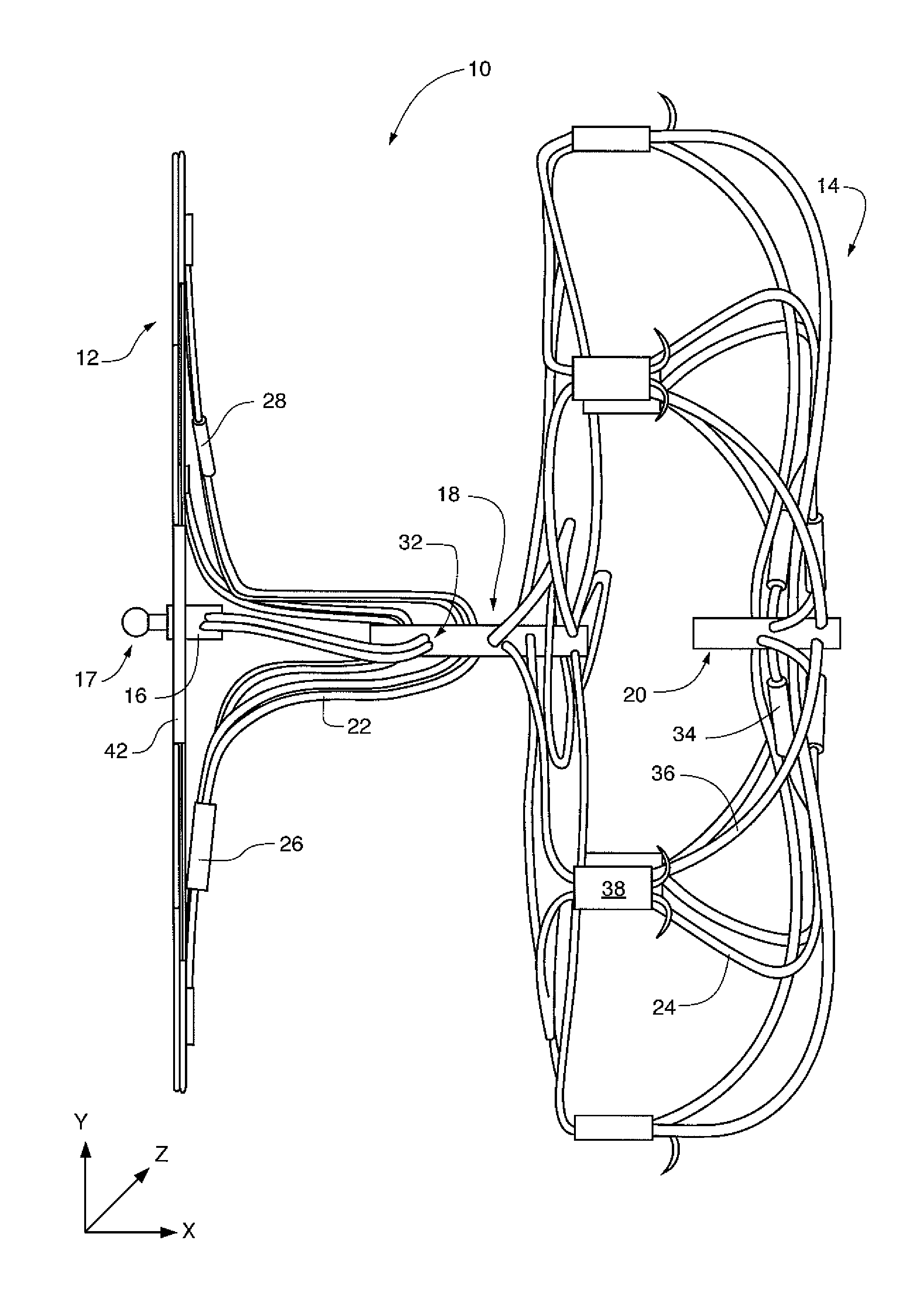
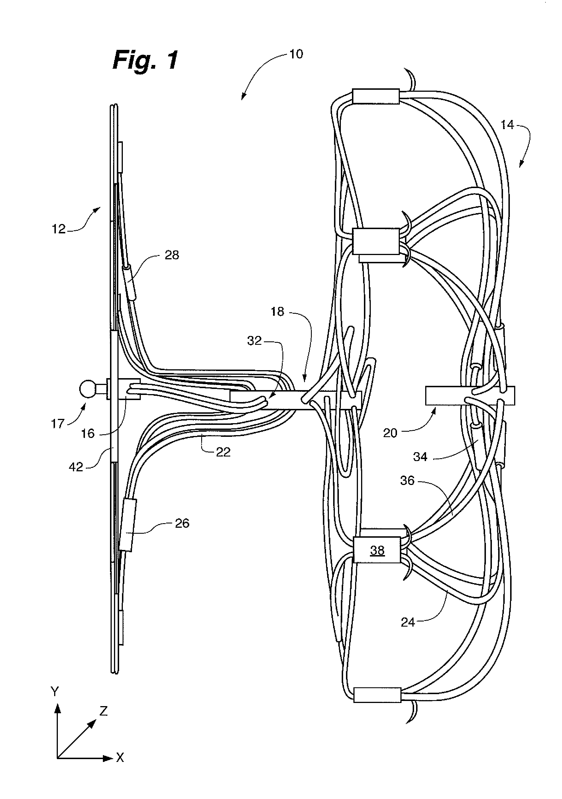
[0020]FIG. 1 shows the LAA device 10 seen from the side in its unstressed or un-deformed shape. The device includes a cap framework 12 and a bulb framework 14. As is common in medical devices the frameworks are manufactured primarily from Nitinol with a “shape memory” shape heat set during manufacture. The device assumes this shape in the un-deformed or unstressed condition. The interconnecting posts are made from titanium or any other compatible material. In general the wires are multi-stranded although monofilament wire may be substituted selectively. The use of multiple strands wire is preferred.

[0021]The cap framework is made up of a collection or set of wire loops, typified by the wire loop 22. Each wire loop for the cap framework is formed by a single Nitinol wire that passes though a hole in the proximal post 16, and a hole in the intermediate post 18. A crimp connector collars typified in the figure by crimp connector collar 26 or crimp connector collar 28 is used to collect...


PUM


Abstract

A medical device implant for the left atrial appendage of a patient's heart to prevent strokes. The device includes a cap that overlies the opening of the LAA connected to a bulb in the LAA. Discontinuous segmented sails attached to the cap promote tissue growth over the device. The device maybe repositioned and redeployed during implantation.

Description

CROSS REFERENCE TO RELATED CASES[0001]This application is a continuation-in-part of U.S. patent application Ser. No. 13 / 400,968 filed Feb. 21, 2012, entitled Left Atrial Appendage Occlusion Device.FIELD OF THE INVENTION[0002]The present invention related to implanted devices for use in occluding the left atrial appendage of patients. The device includes structures that permit the device to be easily retrieved and redeployed.BACKGROUND OF THE INVENTION[0003]It is widely understood that the occlusion of the left atrial appendage of the human heart will prevent strokes. The mechanism of action is that clots present within the left atrial appendage can become entrained into the general circulation and be transported to the brain where the clots can occlude arterial vessels causing an ischemic stroke.[0004]Devices that have received significant clinical study include the “Plaato” device described in U.S. Pat. No. 6,152,144 among others, and the “Watchman” device described in U.S. Pat. No...

Claims


Application Information

Patent Timeline
Patent Type & Authority Patents(United States)
IPC IPC(8): A61B17/12A61B17/00
CPCA61B17/12122A61B17/12172A61B2017/00867A61B2017/12054
Inventor ERZBERGER, GARY S.CHIN, DARASANDGREN, ROBERT T.CORCORAN, MICHAEL PATRICK
Owner ATRIAL SOLUTIONS INC
Learn More