
Pneumatic tire

a pneumatic tire and tire body technology, applied in the field of pneumatic tires, can solve the problems of easy conspicuous misprinting at the outer edge, incongruous printed area, etc., and achieve the effects of reducing the air resistance when the tire is rotated, reducing the sense of incongruity, and increasing decorativeness

Active Publication Date: 2017-01-31
BRIDGESTONE CORP
View PDF14 Cites 0 Cited by
  • Summary
  • Abstract
  • Description
  • Claims
  • Application Information

AI Technical Summary

Benefits of technology

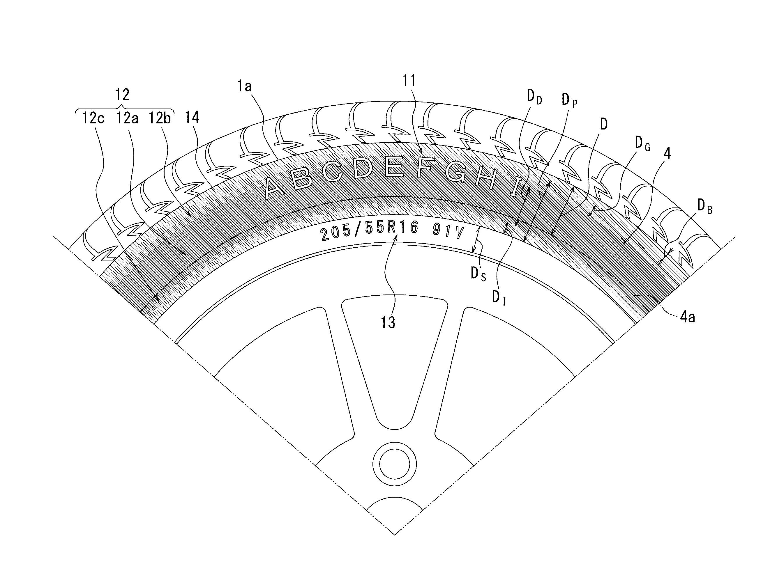
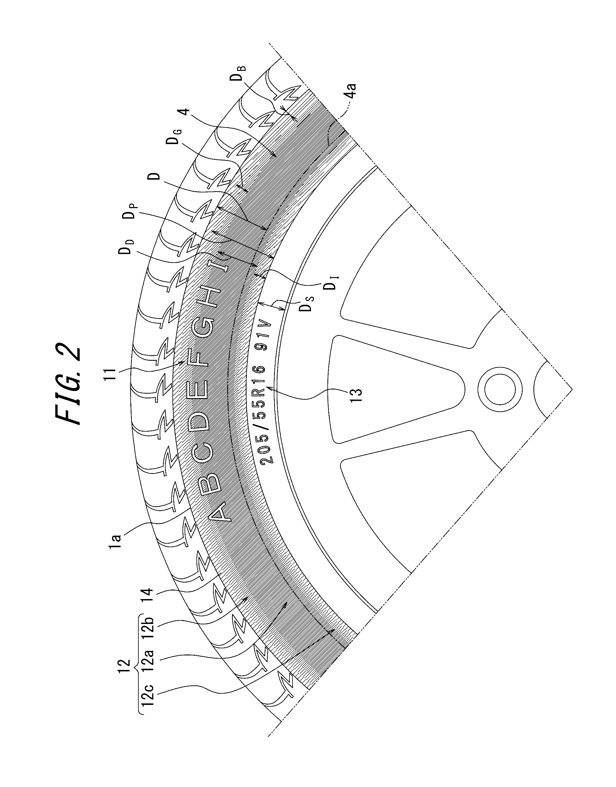
[0010]It is an object of the present invention effectively to solve such conventional problems occurring when printing with a printing device by providing a tire with reduced air resistance when rotated with load applied thereon, greatly increased decorativeness at the outer surface of the tire side portion by printing, and increased yield of printed product tires by reducing the noticeability of misprinting due to unevenness or runny ink.
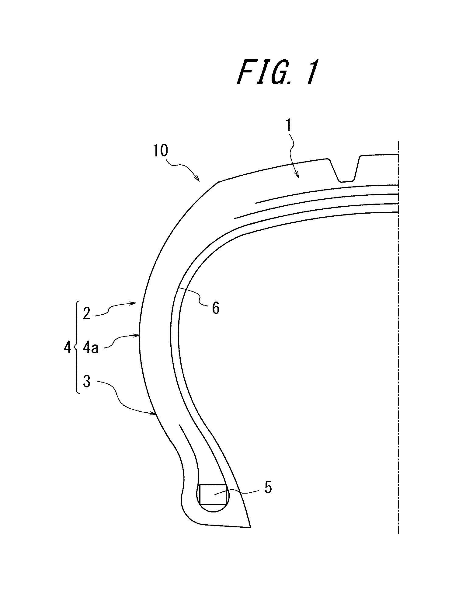
[0020]In the tire according to the present invention, the annular gradation portion is provided on the outer surface of the tire side portion at least on the tire radial direction outer side of the design portion in the annular decoration printing portion, and in the gradation portion, the value of the printing design is incrementally changed in the tire radial direction. Therefore, decoration can be formed by flat printing, without raising or recessing the outer surface of the side portion, thereby reducing the air resistance when the tire is rotated. Forming the gradation portion also relieves the sense of incongruity felt by the viewer, thus greatly increasing the decorativeness, and reduces the noticeability of misprinting.

Problems solved by technology

Therefore, a problem arises in that a viewer strongly perceives the boundary between the area where the marks or decoration are printed and the area without printing and finds the printed area to be incongruous, not blending with the tire side portion (referred to below as a “sense of incongruity”).
This leads to the problem that misprinting at the outer edge easily becomes conspicuous.

Method used


Image

  • Pneumatic tire
  • Pneumatic tire
  • Pneumatic tire

Examples


example 1

[0064]As described below, the sense of incongruity felt by a viewer was investigated for Example Tires 1 to 26 according to the present invention and a Comparative Tire that were produced to have design portions formed thereon. Specifically, 50 viewers observed the produced tires and answered a questionnaire regarding whether they felt a sense of incongruity. For each tire, the number of viewers not feeling a sense of incongruity was totaled. Table 1 shows the results. Using the investigation results for the Comparative Tire as a control, the investigation results for each tire are indicated as an index. A greater value (decorativeness) for the sense of incongruity indicates less of a sense of incongruity for the tire and better decorativeness.

[0065]For the Example Tires 1 to 26, the size was 195 / 65R15, and on the tire side portion, which had a width of 75 mm in the tire radial direction, an interval of 15 mm in the tire radial direction was provided from the rim line position, and ...

example 2

[0071]As described below, 50 each of Example Tires 1 and 20 according to the present invention and the Comparative Tire were produced, and the number of tires for which misprinting was discovered due to unevenness or runny ink was investigated. Table 2 shows the results. The Example Tires 1 and 20 and Comparative Tire produced here were the same as the Example Tires 1 and 20 and Comparative Tire of Example 1. In other words, in Example Tire 1, the gradation portion was formed only on the outer side of the decoration portion in the tire radial direction, and in Example Tire 20,the gradation portion was formed on the outer and inner sides in the tire radial direction. In the Comparative Tire, no gradation portion was formed.

[0072]

TABLE 2Example Tire 1Example Tire 20Comparative TireOuter sideYESYESNOgradationInner sideNOYESNOgradationNumber of103misprints

[0073]The results indicate that for Example Tires 1, and 20, provided with the gradation portion on the tire radial direction outer s...


PUM


Abstract

A tire includes an annular decoration printing portion, at least a portion thereof being provided on an outer surface of a side portion further toward a tire radial direction outer side than a tire maximum width position. The decoration printing portion includes an annular design portion and an annular gradation portion provided at least on the tire radial direction outer side of the design portion. The gradation portion incrementally decreases in value outward in the tire radial direction, with a value of 100% being a pure color and a value of 0% being pure black in an HSV color space.

Description

CROSS REFERENCE TO RELATED APPLICATIONS[0001]This application is a National Stage of International Application No. PCT / JP2012 / 077813, filed on Oct. 22, 2012, which claims priority from Japanese Patent Application No. 2011-232088, filed on Oct. 21, 2011, the contents of all of which are incorporated herein by reference in their entirety.TECHNICAL FIELD[0002]The present invention relates to a pneumatic tire (referred to below as a “tire”) provided with an annular decoration printing portion on an outer surface of a side portion that includes a sidewall and a bead portion. In particular, a technique is proposed for adding greater value by increasing the tire's decorativeness and for achieving an external appearance sufficiently differentiated from other tires.BACKGROUND ART[0003]Techniques are known for displaying marks on the outer surface of a side portion that includes a sidewall and a bead portion. The marks are composed of characters, graphics, symbols including barcodes, or the l...

Claims


Application Information

Patent Timeline
Patent Type & Authority Patents(United States)
IPC IPC(8): B60C13/00B60C13/04
CPCB60C13/001B60C13/04
Inventor HIMURO, YASUOMIYASAKA, ATSUSHI
Owner BRIDGESTONE CORP
Learn More