Closure device

Active Publication Date: 2017-01-31
FIDLOCK GMBH
View PDF27 Cites 10 Cited by
  • Summary
  • Abstract
  • Description
  • Claims
  • Application Information

AI Technical Summary

Benefits of technology

[0031]The magnet arrangement at the connector and at the slide can be designed such that the force of magnetic repulsion just is at a maximum when the engagement between the connector and the housing (i.e. for example between the pin with its latching portion at the connector and the detent spring element at the slide) is released and the connector thus can be removed.
[0032]A magnetic repulsion on opening of the closure device can be reached in that magnetically like poles are approached towards each other when shifting the slide in the opening direction. A magnetic repulsion however also is obtained e.g. when magnets which in the closed position oppose each other with unlike poles in a magnetically attracting way, on opening are moved towards each other tangentially with their opposed pole surfaces. When the magnets have an at least approximately identical pole shape (i.e. when the surfaces w

Problems solved by technology

During the opening movement of the slide an action of force on the connector, for example due to friction, also can occur, which connector thus is loaded relative to the housing and possibly may cant

Method used


Image

  • Closure device
  • Closure device
  • Closure device

Examples


Example

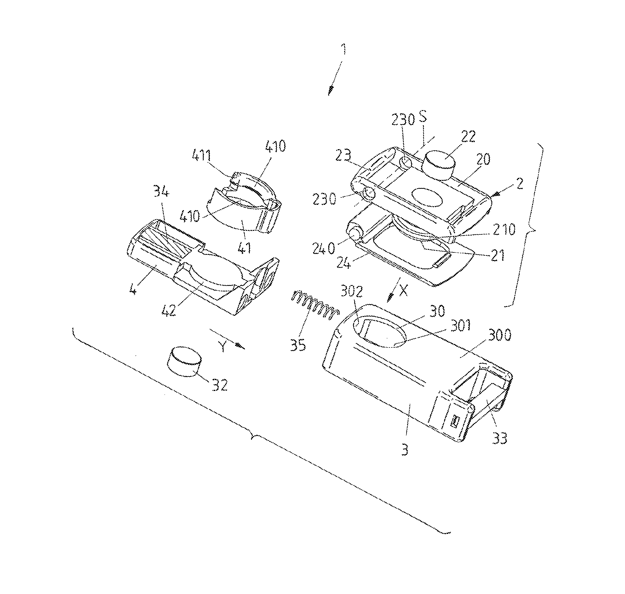
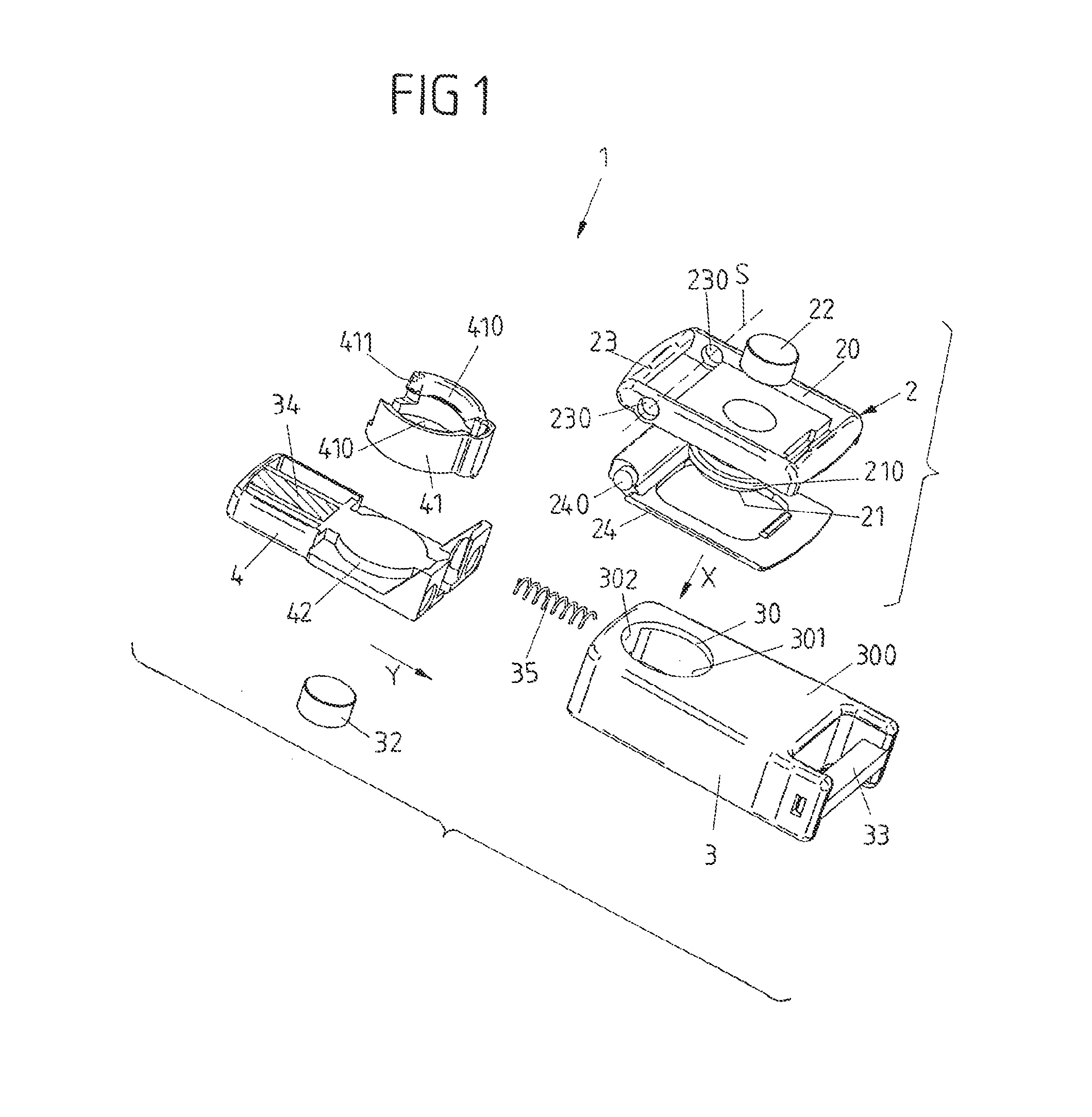
[0048]FIGS. 1, 2 and 3A to 3D show a closure device 1 which includes a connector 2, a housing 3 and a slide 4 shiftably arranged at the housing 3.

[0049]The closure device 1 serves for connecting two parts, for example as closure for a bag, a backpack or another flap, as connecting device for connecting two belts or cables or for connecting two other parts. One part here is attached to the connector 2, while the other part is connected with the housing 3. In a closed position, shown in FIG. 3B, the connector 2 is held at the housing 3, so that the two parts are connected with each other via the connector 2 and the housing 3. In an open position, shown in FIGS. 3A and 3D, the connector 2 and the housing 3 are separated, so that there is no connection between the parts.

[0050]In the closure device 1 the connector 2 includes a body 20 with a fastening device 23 for connecting a part (the fastening device 23 for example can be designed as thread onto which a fastening part can be screwed ...


PUM


Abstract

A closure device for connecting two parts is provided. The closure device includes a connector, a housing which includes a connector receptacle, into which the connector can be inserted in a closing direction for closing the closure device, a slide shiftably arranged at the housing, which for opening the closure device is shiftable along an opening direction different from the closing direction, a detent spring element which in a closed position of the closure device latchingly holds the connector at the housing and for opening the closure device can be moved out of engagement with the connector by shifting the slide in the opening direction, in order to release the connector from the housing, so that in an open position of the closure device the connector is separated from the housing, and at least one guide element which guides the connector on insertion into the connector receptacle for closing the closure device along the closing direction into the closed position and supports the connector against tilting relative to the closing direction when the slide is shifted for opening the closure device.

Description

CROSS-REFERENCE TO RELATED APPLICATIONS[0001]This application is the United States national phase of International Application No. PCT / EP2012 / 063396 filed Jul. 9, 2012, and claims priority to German Patent Application No. 10 2011 086 960.3 filed Nov. 23, 2011, the disclosures of which are hereby incorporated in their entirety by reference.BACKGROUND OF THE INVENTION[0002]Field of the Invention[0003]This invention relates to a closure device for connecting two parts.[0004]Description of Related Art[0005]Such closure device includes a connector and a housing with a connector receptacle, into which the connector can be inserted in a closing direction for closing the closure device. On the housing, a slide is arranged in a shiftable way, which for opening the closure device can be shifted along an opening direction different from the closing direction.[0006]Such closure devices for example serve for connecting two belts, as closure for a bag, a backpack, a suitcase or a box, as closing ...

Claims


Application Information

Patent Timeline
IPC IPC(8): F16B21/00A44B11/25A44B11/26A45C13/10B65D43/20A45C13/12E05B47/00H01F7/02E05B65/52E05B83/38E05B63/00
CPCB65D43/20A44B11/258A44B11/266A45C13/1069A45C13/1092A45C13/123E05B47/0038E05B65/52E05B83/38H01F7/0263A44D2203/00E05B2063/0026
Inventor FIEDLER, JOACHIM
Owner FIDLOCK GMBH
Why Eureka
Try Eureka