Heat Pipe with Inner Zeolite Coated Structure

a technology of heat pipe and inner zeolite, which is applied in the direction of indirect heat exchangers, lighting and heating apparatus, etc., can solve the problems of wicks being easily oxidized, failure, and only transferring heat upwards, and achieves maximum evaporation heat transfer capability and capillary force. , the effect of high efficiency

Inactive Publication Date: 2018-03-22
INST NUCLEAR ENERGY RES ROCAEC
View PDF6 Cites 3 Cited by
  • Summary
  • Abstract
  • Description
  • Claims
  • Application Information

AI Technical Summary

Benefits of technology

The present invention provides a heat pipe with an internal structure that has a zeolite coating on the inner surface. This heat pipe has high efficiency and is limitless in size without the need for air isolation. The zeolite coating has small pores that enable maximum evaporation heat transfer capability and capillary force. The heat pipe has a shell with an evaporator section and a condenser section, and the zeolite coating is fabricated on the inner surface with a material comprising zeolite, binder, and additive. This heat pipe is suitable for use in various applications such as refrigerators, heating systems, and cooling systems.

Problems solved by technology

Yet, it is obvious that thermosyphon can only transfer heat upwardly.
Besides, the overall length of the heat pipe is limited by the size of the sintering furnace so it is only suitable for a heat pipe with a length less than 50 centimeters (cm).
In addition, air isolation is required after sintering; otherwise the wick may be easily oxidized and fail.
Although the above method suits various sizes of pipe, the pore size is too big so that the evaporation heat transfer capability and capillary force is insufficient.
According to the above prior arts, there is no effective way to at the same time solve the problems of size limitation, wick oxidation during manufacturing, insufficient evaporation heat transfer capability and capillary force.
Hence, the prior arts do not fulfill all users' requests on actual use.

Method used


Image

  • Heat Pipe with Inner Zeolite Coated Structure
  • Heat Pipe with Inner Zeolite Coated Structure
  • Heat Pipe with Inner Zeolite Coated Structure

Examples


Embodiment Construction

[0018]The following description of the preferred embodiment is provided to understand the features and the structures of the present invention.

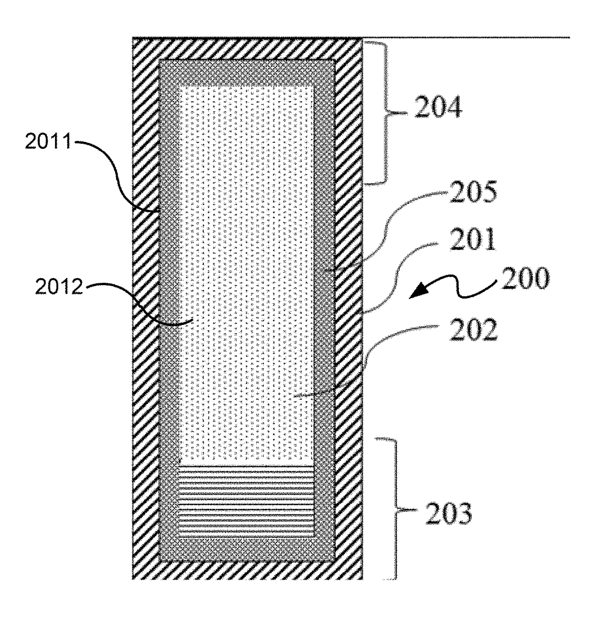
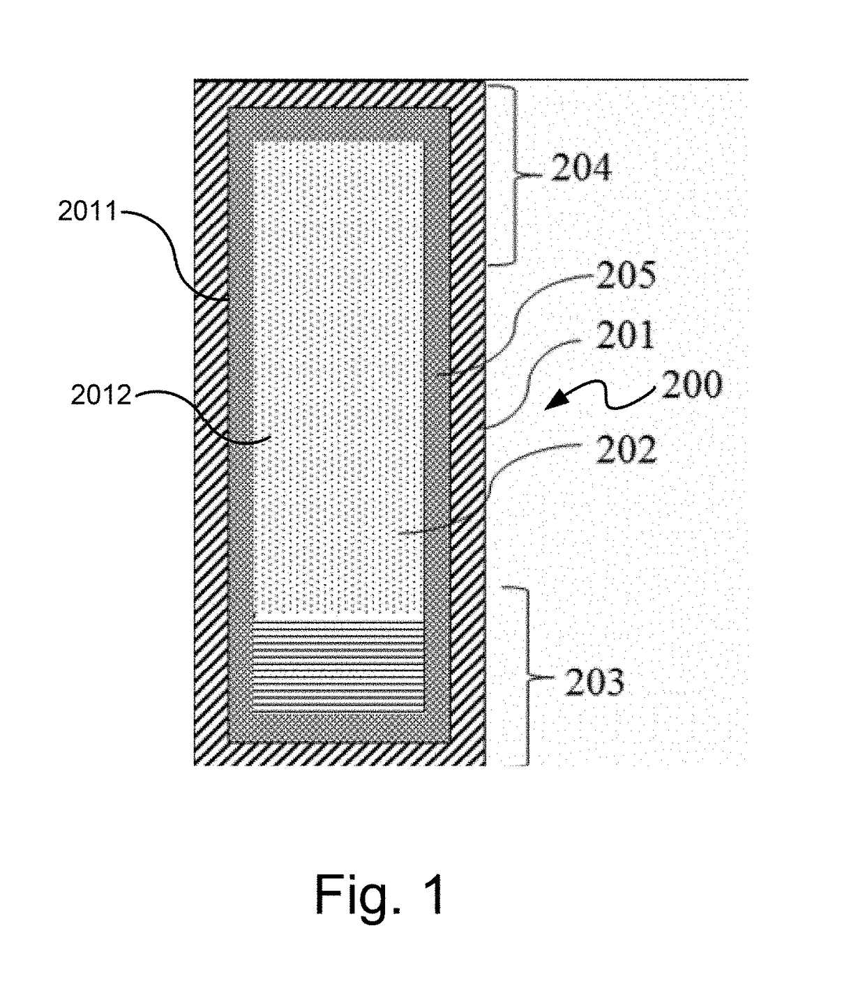
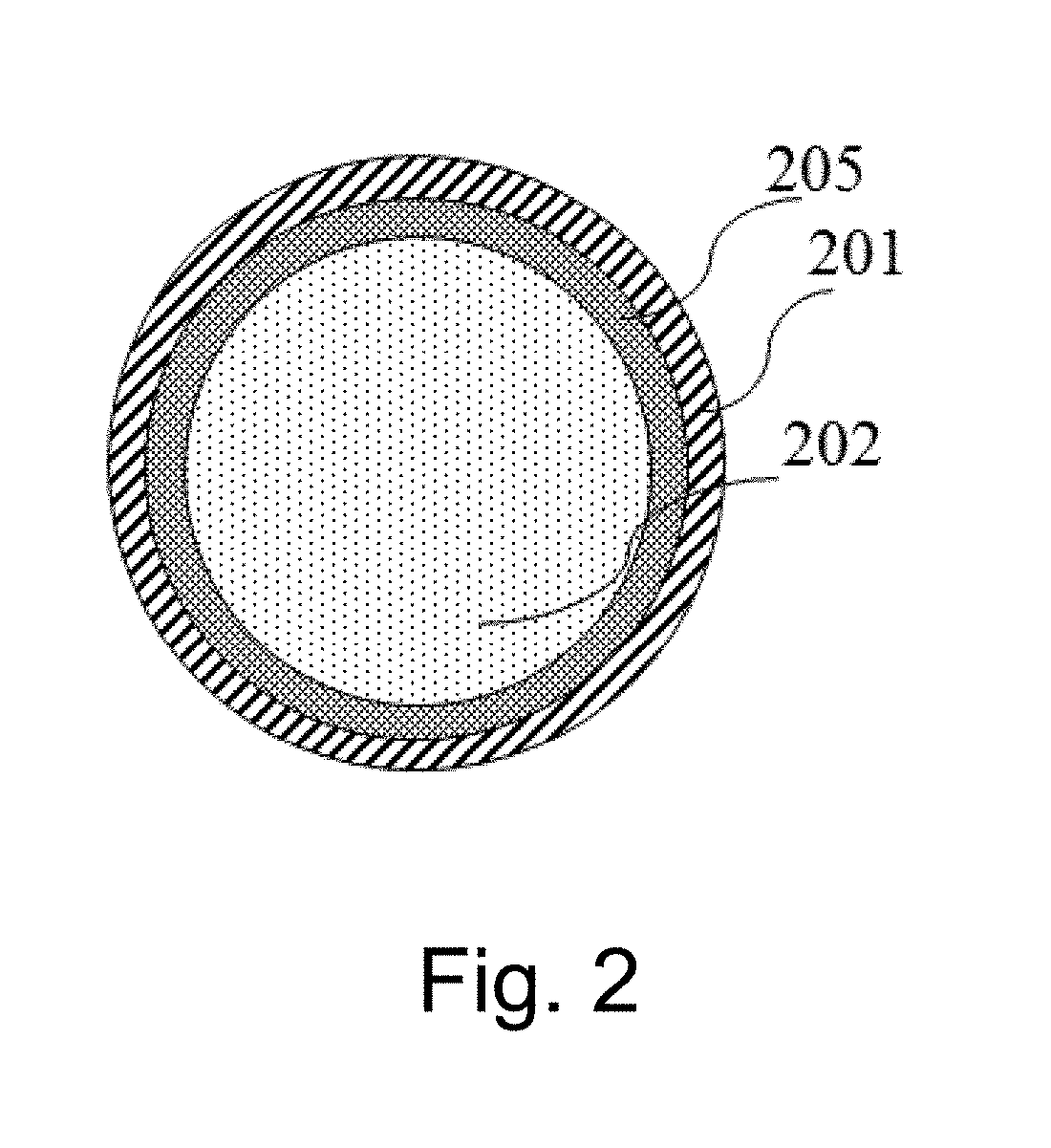
[0019]Please refer to FIG. 1˜FIG. 6, which are a vertical cross-sectional view showing a preferred embodiment according to the present invention; horizontal cross-sectional views showing a zeolite single-layer coating and a zeolite dual-layer coating; a flow block diagram showing fabrication of the present invention; a cross-sectional view showing a zeolite coating on surface of micro grooves; and a view showing zeolite crystals. As shown in the figures, the present invention is a heat pipe 200 for cooling or recycling waste heat with high efficiency, comprising a shell 201, and a zeolite coating 205.

[0020]The shell 201 has an evaporator section 203 and a condenser section 204 located away from the evaporator section 203. The shell 201 has an inner surface 2011. The inner surface 2011 surrounds an enclosed chamber 2012. The enclosed chamber 2...


PUM


Abstract

The heat pipe comprises a shell and an inner zeolite coated structure. The shell has an inner surface. The inner surface surrounds an enclosed chamber. The chamber is partially filled with a working fluid in a vacuum. The working fluid may be changed into a liquid phase or a gas phase by following temperature change. The coating material comprises a zeolite, a binder and an additive. The material is sintered on the inner surface of the heat pipe. Consequently, the zeolite coating is formed between the inner surface and the enclosed chamber. Thus, the present invention uses a porous material of zeolite with pore size smaller than grooves and meshes to have excellent evaporation heat transfer and capillary force. The zeolite coating of the present invention does not fail without air isolation. The present invention is inner manufactured under atmospheric condition so has no size limitation.

Description

TECHNICAL FIELD OF THE INVENTION[0001]The present invention relates to the inner structure of heat pipe; more particularly, relates to the heat pipe with zeolite coated on the inner surface for capillary wick for cooling and waste heat recovery.DESCRIPTION OF THE RELATED ARTS[0002]Heat pipe is most commonly used in the following fields: cooling of electronic components and electrical devices, and waste heat recovery of equipment or machinery. Currently much waste heat is discharged directly or indirectly without recycling. Directly-discharged waste heat mostly exists in the exhausted gas and liquid, and its sources include boilers, burners, incinerators, furnaces, combustion engines and other heating facilities. Indirect-discharged heat sources are the cooling air or cooling water loops that are used to remove the heat of facilities for protection, or the heat of processes for next handling station.[0003]The first prior art in FIG. 7 is a thermosyphon 100. The shell 101 is made of m...

Claims


Application Information

Patent Timeline
IPC IPC(8): F28D15/04
CPCF28D15/046
Inventor LI, HENG-YITSAI, MENG-CHANGWANG, TO-MEI
Owner INST NUCLEAR ENERGY RES ROCAEC
Why Eureka
Try Eureka