Adaptive self-centering apparatus and method for seismic and wind protection of structures

a self-centering apparatus and structure technology, applied in the direction of shock absorption devices, shock proofing devices, gearing, etc., can solve the problems of affecting the mental and physical health of the occupants, the buffeting of wind turbulence, and the vibration of vortex-induced vibrations of the structure, so as to increase the restoring force of the device, increase the acceleration, and reduce the effect of mass

Active Publication Date: 2021-10-05
ARROWHEAD CENT
View PDF28 Cites 1 Cited by
  • Summary
  • Abstract
  • Description
  • Claims
  • Application Information

AI Technical Summary

Benefits of technology

[0072]The analytical formulations and the experimentations of the ASCD are performed for quasi-static excitations. For dynamic excitations, the inertia effects may modify the force deformation relationships. The inertia effect of the components, other than the friction wheel, is expected to be negligible, due to their smaller mass. Taking the polar moment of inertia (Jf) of the friction wheel into account, Equation 5 is modified as:
[0073]During loading, the dynamic effect is expected to increase the restoring force of the device with increasing acceleration. This results in lesser displacement demand. Further, the dynamic effect is absent during unloading, as the friction wheel remains static. Hence, the self-centering mechanism of the device will not be affected.
[0074]Other than the counterweight force and the friction coefficients, the ASCD has several dimensions (see Table 1), such as, a, b, c, R, h, r, rr, that affect the force-deformation response, especially the nonlinear hardening, energy dissipation, and maximum restoring force. The parameters R and rr are directly proportional to the restoring force of the ASCD, as observed from Equations 8-14.
[0075]Owing to its small magnitude, the influence of rr on the ASCD force is negligible. The derived parameter I (Equation 7, FIGS. 6 and 8) depends upon c, h, and the displacement (x) of the ASCD. Accordingly, the maximum and minimum values of I can be obtained as:
[0076]lmax=h2+(c+xmax)2,lmin=h2+c2(Equation⁢⁢18)
[0077]The above constraints will also ensure that lever 5 does not get aligned radially to the wheels within the range of operation of the ASCD, which would otherwise cause the apparatus to become locked. The shaded area in FIG. 18 illustrates the allowable ranges for a and b. For the prototype device, as per Table 1, the Imax and Imin values are 128.17 mm and 100.58 mm, respectively. A sensitivity study is carried out by varying a+b and choosing a and b as illustrated in FIG. 19. Although any counterweight can be used and will provide desirable results, the counterweight for all examples in this application was kept constant at 66.92 N. The parameters, except a and b, are adopted as per Table 1. From FIG. 19, it is observed that the nonlinear hardening, energy dissipation, and maximum restoring force tend to decrease with increasing a+b. Also, for the same a+b, the maximum restoring force and energy dissipation tend to increase with increasing a / b ratio. Hence, it is recommended to design the ASCD with minimum a+b and maximum a / b ratio.

Problems solved by technology

Owing to their slender shape, tall structures often experience along-wind turbulence buffeting and cross-wind vortex-induced vibrations.
Further, prolonged exposure to vibrations affects the mental and physical health of the occupants, and may lead to migraines and nausea.
This type of structure might encounter seismic forces huge enough to incur damage.
These buildings may encounter lower forces, but nevertheless experience deformations large enough to suffer damage.
However, it appears that structural designers in the United States are not feeling confident in using seismic protective systems as suggested by the design codes, and the additional cost of outfitting buildings with protective devices precludes the designers from using them.
However, the energy dissipation in TFP is greater at moderate deformations but decreases significantly at larger deformations.
This often leads to larger deformations that can damage the TFP itself for extreme events.
Further, the TFP cannot achieve full self-centering when the lateral load is removed.
However, TMD loses its effectiveness even with 5% mistuning.
Since viscous dampers (VD) suffer the drawback of not being functional at low frequency wind excitations, linear and nonlinear VDs have been implemented either in large numbers or in combination with passive or active TMDs and / or tuned liquid column dampers (TLCDs) for wind-induced vibration mitigation.
Residual deformation is a common problem when a structure experiences inelastic deformations during a seismic event.

Method used


Image

  • Adaptive self-centering apparatus and method for seismic and wind protection of structures
  • Adaptive self-centering apparatus and method for seismic and wind protection of structures
  • Adaptive self-centering apparatus and method for seismic and wind protection of structures

Examples


case 1

g: Right Cartridge Moves Towards Right

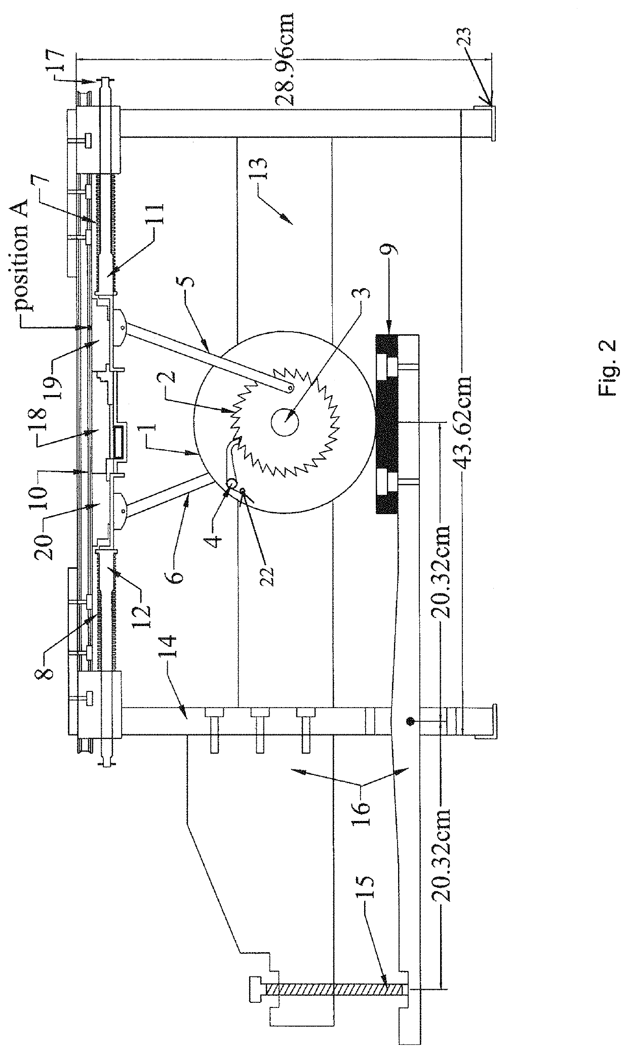
[0053]Referring now to FIGS. 6 and 7, F is the external lateral force acting towards the right. The component of this force (BD) that is transferred to right lever 5 is Fa. P is the force exerted on friction wheel 1 by pad 9 to produce the breakaway friction force μarP. Although pad 9 is generally referred to as a “rubber pad” such description is merely intended to apprise the reader of the most preferred embodiment and other materials, including but not limited to other elastic or flexible materials, can be used and will provide desirable results. Here μar is the frictional coefficient between friction pad 9 and friction wheel 1 (aluminum on rubber in the most preferred embodiment). Accordingly, in one embodiment, one or more brake pads could also be used. Likewise, although the figures illustrate an embodiment wherein the friction pad is forced upward against an outer edge of the friction wheel, in one embodiment, a pair of friction pads can b...

case 2

ing: Right Cartridge Moves Towards Left

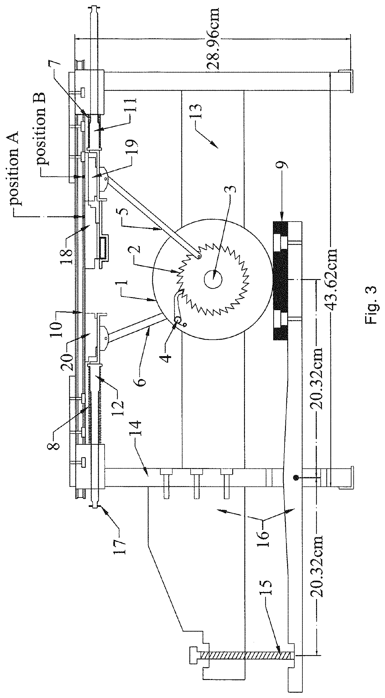
[0064]As best illustrated in FIGS. 8 and 9, when the right cartridge moves from right to left, the ratchet wheel rotates in a clockwise direction. The friction wheel remains static as the pawl ratchets over the ratchet wheel and thus the breakaway friction force between the friction pad and the friction wheel need not be overcome by the active force F.

From the free body diagram of joint B (see FIG. 9),

Fa=F / cos(θ2)  (Equation 9)

wherein Fa is the compressive force in the member BD.

From the free body diagram of joint D (see FIG. 9), resolving the force Fa into tangential (Ft) and radial (Fr) components gives

Ft=Fa sin(ω)

Fr=Fa cos(ω)  (Equation 10)

wherein Fr generates the friction force (μssFr) between the ratchet wheel and the shaft (steel on steel). μss is the friction between steel on steel.

[0065]The reactive frictional moment Mss (see Equation 3) due to the relative motion between the ratchet wheel and the shaft will act as illustrated in FIG. 9...

example 1

Instrumentational Setup on the ASCD for Experiments

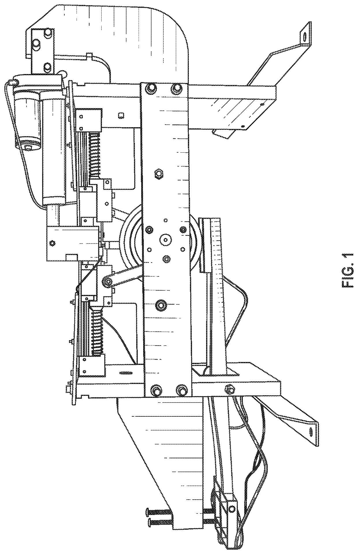
[0084]FIG. 10 illustrates an experimental setup of the device that was constructed wherein center cartridge 18 was connected to actuator 21, which was powered by a 12V DC supply. This cartridge also had tension-compression load cell 23 attached to it, which measured the force applied to cartridge 18 by actuator 21.

[0085]The counterweight force was measured by another set of load cells that were attached to the tip of counterweight screw 15. The tests were carried out in a displacement controlled fashion. Incremental displacements were applied to the actuator manually by using a two-way control regulator. The magnitudes of different parameters of the ASCD, including the friction coefficients, are illustrated in the following table.

[0086]

TABLE 1Parameters of the ASCDSI. No.SymbolMeaningMagnitudeUnit1a|BD|101.60mm.2b|OD|31.753c|EA|58.904RRadius of the friction wheel63.505h|OE|81.536rRadius of the shaft11.817rrMean radius of the ratchet...


PUM


Abstract

An adaptive self-centering device (ASCD) which uses one or more ratchet-pawl mechanisms. The hysteretic slip force of the ASCD preferably comes from a friction mechanism. The self-centering originates from the ratcheting of the pawl over the ratchet wheel and a self-centering device, in response to a force from an apparatus such as a spring. The nonlinear hardening of the apparatus, which conforms to the favorable adaptive behavior sought in modern day passive devices, stems from the mechanism of the lever within the apparatus that transforms the linear motion into rotatory motion.

Description

CROSS-REFERENCE TO RELATED APPLICATIONS[0001]This application claims priority to and the benefit of the filing of U.S. Provisional Patent Application No. 62 / 505,489, entitled “Adaptive Self-Centering Apparatus and Method for Seismic Protection of Structures”, filed on May 12, 2017, and the specification thereof is incorporated herein by reference.BACKGROUND OF THE INVENTIONField of the Invention (Technical Field)[0002]Embodiments of the present invention relate to a new adaptive self-centering device for structural protection using a combination of a friction-ratchet-pawl-lever mechanism. More particularly, embodiments of the present invention relate to an adaptive self-centering apparatus that is couplable to a structure and which dampens movement of the structure.DESCRIPTION OF RELATED ART[0003]According to the Insurance Information Institute, the average annual loss of insured property from earthquake and tsunami was $2.8 billion globally from 2014 through 2017. Per the Federal E...

Claims


Application Information

Patent Timeline
Patent Type & Authority Patents(United States)
IPC IPC(8): E04H9/02F16D49/00F16D41/12F16H21/44E04B1/98
CPCE04H9/0215E04H9/02F16D41/12F16D49/00F16H21/44E04B1/98E04H9/021F16D2121/22F16D51/00F16D55/22F16F7/06F16F2232/06F16F7/023
Inventor RAY, TATHAGATATANG, YU-PINGPARK, CHARLES
Owner ARROWHEAD CENT
Why Eureka
Try Eureka