Gyromotor

a gyromotor and gearbox technology, applied in the direction of motors, machines/engines, mechanical equipment, etc., can solve the problem that the thrust to weight is not sufficient to provide lift-off against earth gravity, and achieve the effect of maximum resistance torque and resistance linear for

Inactive Publication Date: 2012-02-02
VRANISH JOHN M
View PDF1 Cites 7 Cited by
  • Summary
  • Abstract
  • Description
  • Claims
  • Application Information

AI Technical Summary

Benefits of technology

[0016]Gyromotor is a type of action and reaction motor which generates thrust without plume ejection. Whereas rockets react equal and opposite to ejected mass momentum, Gyromotor cycles gyroscopes, each mounted on the end of a moment arm, in a back and forth rowing motion to drive a spacecraft, without external mass ejection analogous to rowing a boat. Gyroscope inertial properties are configured to provide maximum resistance torque during the drive stroke and reconfigured to provide minimum torque resistance during the return stroke. The gyroscopes are turned by a moment arm so the torque resistance provides a useful linear force component to drive the spacecraft, with said linear force greater during the drive stroke than the return stroke, analogous to an oar in water during the drive stroke and in air during the return stroke. The space craft moves in reaction to the net linear forces and momentum is conserved. The torques and forces are pseudo and are generated by change of gyroscope spin axis during said moment arm rotation, similar to centrifugal and coriolis effect pseudo forces. The Gyromotor Invention will provide maximum resistance torque and resistance linear force during the Drive Stroke because the gyroscopes are each spinning and are oriented such that the spin axis of each is perpendicular to the axis of moment arm rotation. Maximum net action and reaction force, then depends on minimizing resistance torque and linear reaction force during the return stroke.

Problems solved by technology

The thrust to weight is not sufficient to provide lift-off against earth gravity.

Method used


Image

  • Gyromotor
  • Gyromotor
  • Gyromotor

Examples


Embodiment Construction

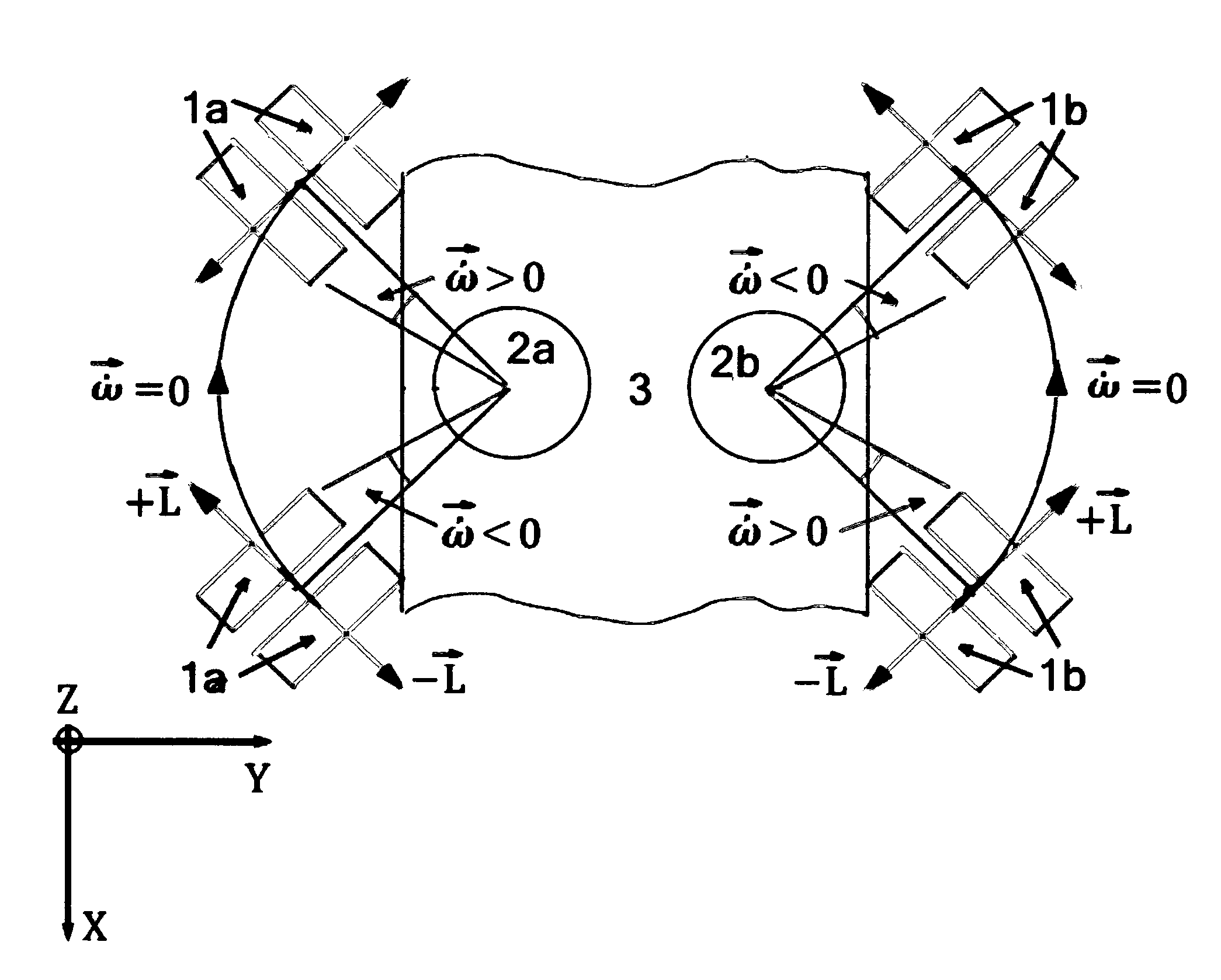
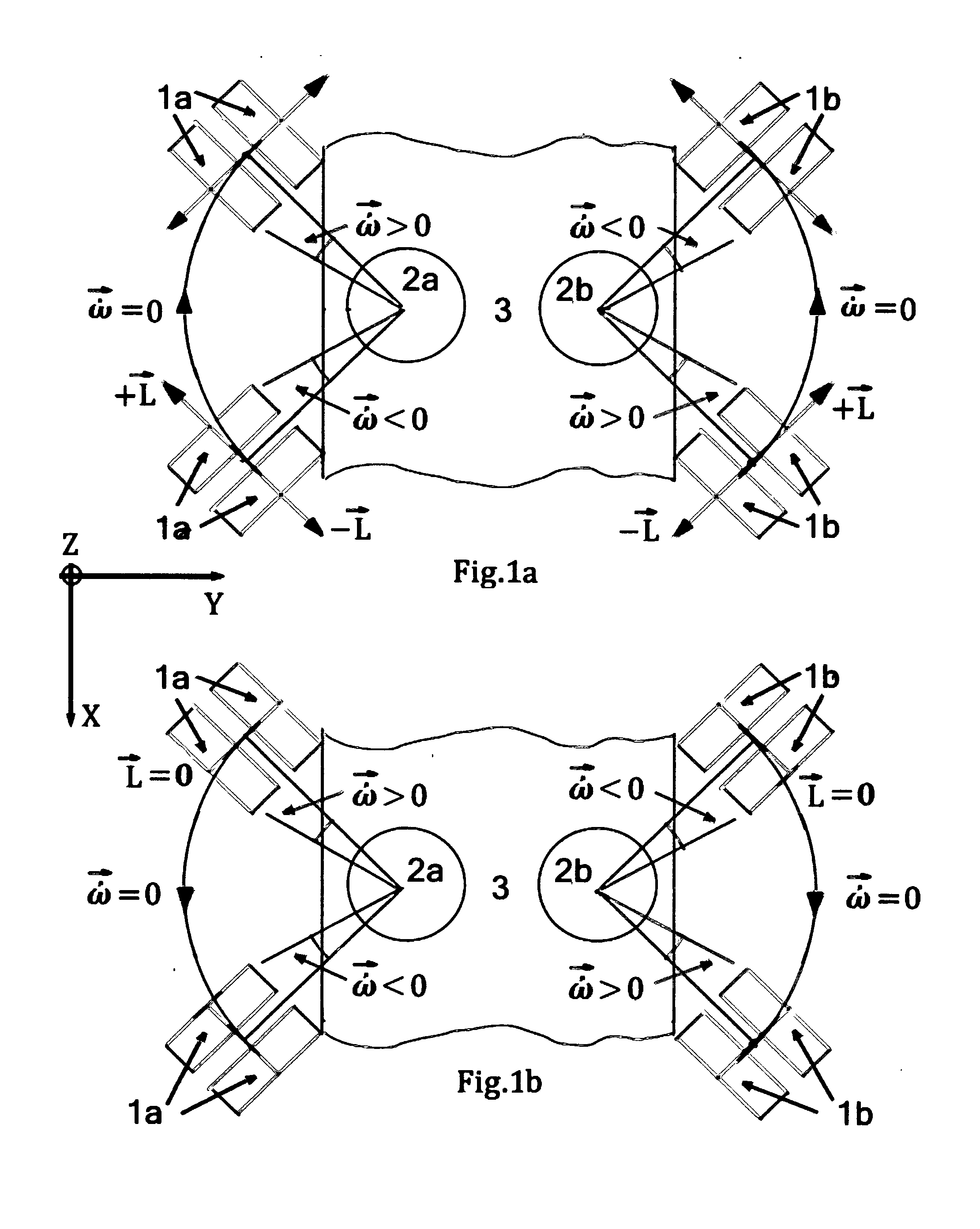
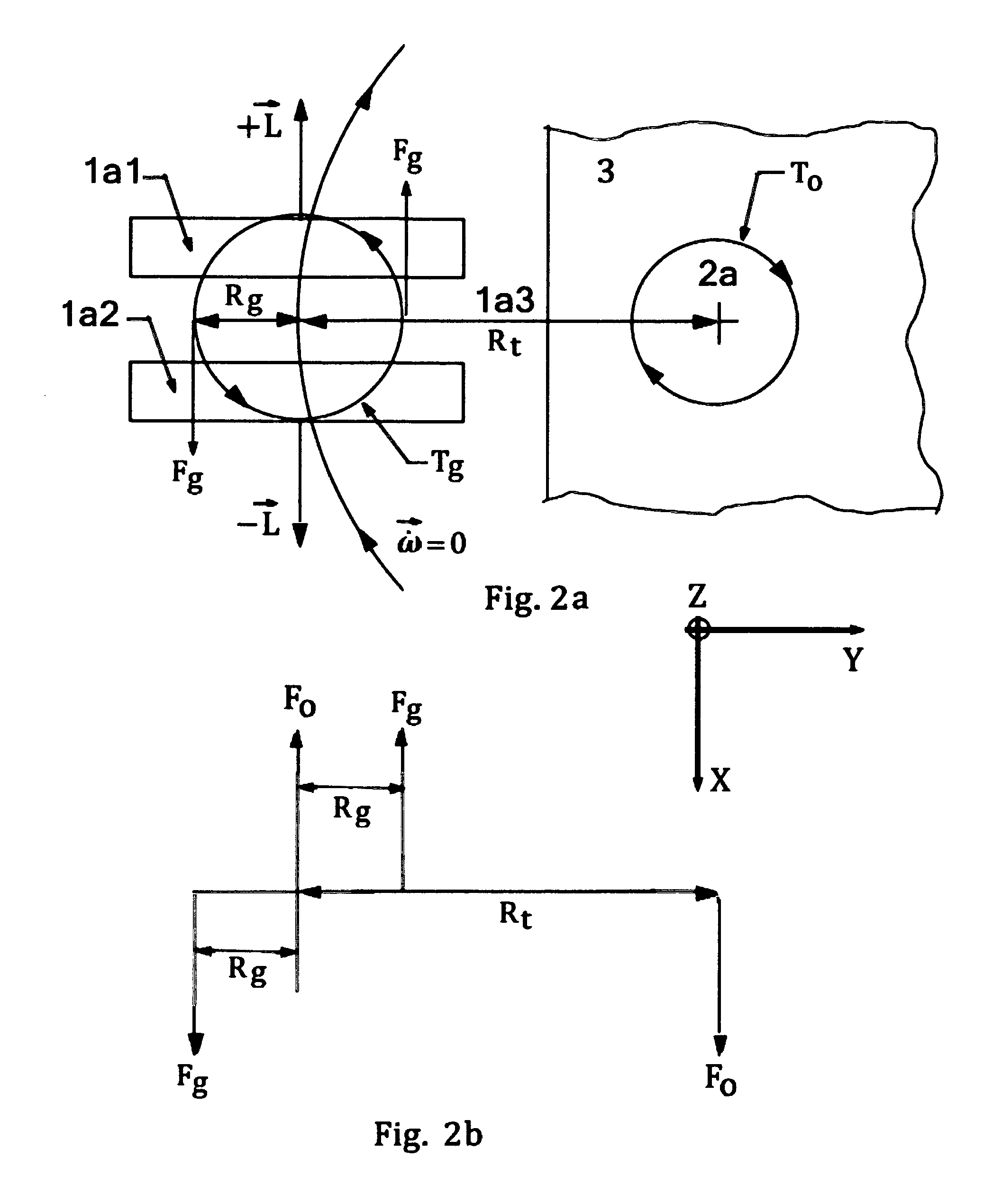
[0032]In accordance with the present invention, a Gyromotor includes: 1. a Gyroscope Arm System, 2. A Motor Control System to control and motivate said Gyroscope Arm System, 3. a Housing for 1 and 2. The Gyroscope Arm System includes a Left Arm System and a Right Arm System n which each of the two arm systems contains a pair of co-axial gyroscopes mounted on the end of a moment arm. The Motor Control System includes a Left Motor Control System and a Right Motor Control System. The Left Motor Control System rotates the Left Moment Arm and attached gyroscopes and, independently, spins the Left Arm System gyroscopes at angular velocities equal and opposite to each other. The Right Motor Control System rotates the Right Moment Arm and attached gyroscopes and, independently, spins the Right Arm System gyroscopes at angular velocities equal and opposite to each other. For linear travel, the Left and Right Arm Systems are rotated towards and away from each other in a coordinated back and f...


PUM


Abstract

Gyromotor is a type of action and reaction motor which generates thrust without plume ejection. Whereas rockets react equal and opposite to ejected mass momentum, Gyromotor cycles gyroscopes, each mounted on the end of a moment arm, in a back and forth rowing motion to drive a spacecraft, without external mass ejection analogous to rowing a boat. Gyroscope inertial properties are configured to provide maximum resistance torque during the drive stroke and reconfigured to provide minimum torque resistance during the return stroke. The gyroscopes are turned by a moment arm so the torque resistance provides a useful linear pseudo force component to drive the spacecraft, with said linear force greater during the drive stroke than the return stroke, analogous to an oar in water during the drive stroke and in air during the return stroke. The space craft moves in reaction to the net linear pseudo forces and momentum is conserved. The pseudo forces are caused by the change of direction of each gyroscope spin axis during its moment arm rotation, similar to centripetal and coriolis effect, pseudo forces.

Description

[0001]The U.S. patent application claims the priority of U.S. Provisional Application No. 61 / 400,613 filed on Jul. 30, 2010.ORIGIN OF THE INVENTION[0002]The invention was made by John M. Vranish as President of Vranish Innovative Technologies LLC and may be used by John M. Vranish and Vranish Innovative Technologies LLC without the payment of any royalties therein or therefore. The work was done by John M. Vranish on his own time and at his own expense.BACKGROUND OF THE INVENTION[0003]There is a large and growing presence of objects in earth orbit associated with human activity. There is need to maneuver these objects and to have ready access to them and this requires a practical transportation system that works in earth orbit where vacuum and micro gravity conditions prevail. This, in turn, suggests an action and reaction motor is required that runs on renewable energy.[0004]Rockets are the means currently employed and these are severely limited in their usefulness. The prime means...

Claims


Application Information

Patent Timeline
Patent Type & Authority Applications(United States)
IPC IPC(8): F03G3/08
CPCF03G3/08
Inventor VRANISH, JOHN M.
Owner VRANISH JOHN M
Why Eureka
Try Eureka