
Hologram transfer foil, fabrication method of image display element, image display element, and personal authentication medium

a technology of image display element and transfer foil, which is applied in the direction of instruments, hologram nature/properties, and substrates with holograms. it can solve the problems of passport tampering, passport tampering becoming more difficult, and face image, which is recorded by using fluorescent materials, cannot be observed, etc., to achieve easy identification, counterfeiting and tampering. the effect of easy identification

Inactive Publication Date: 2017-01-31
TOPPAN PRINTING CO LTD
View PDF16 Cites 0 Cited by
  • Summary
  • Abstract
  • Description
  • Claims
  • Application Information

AI Technical Summary

Benefits of technology

The present invention focuses on providing a hologram transfer foil that is easy to identify, difficult to counterfeit and tamper, and a fabrication method of an image display element. Additionally, the invention provides an image display element and a personal authentication medium that offer enhanced security features. These technical effects aim to improve the security and authenticity of image display elements and protect against counterfeit and tampering.

Problems solved by technology

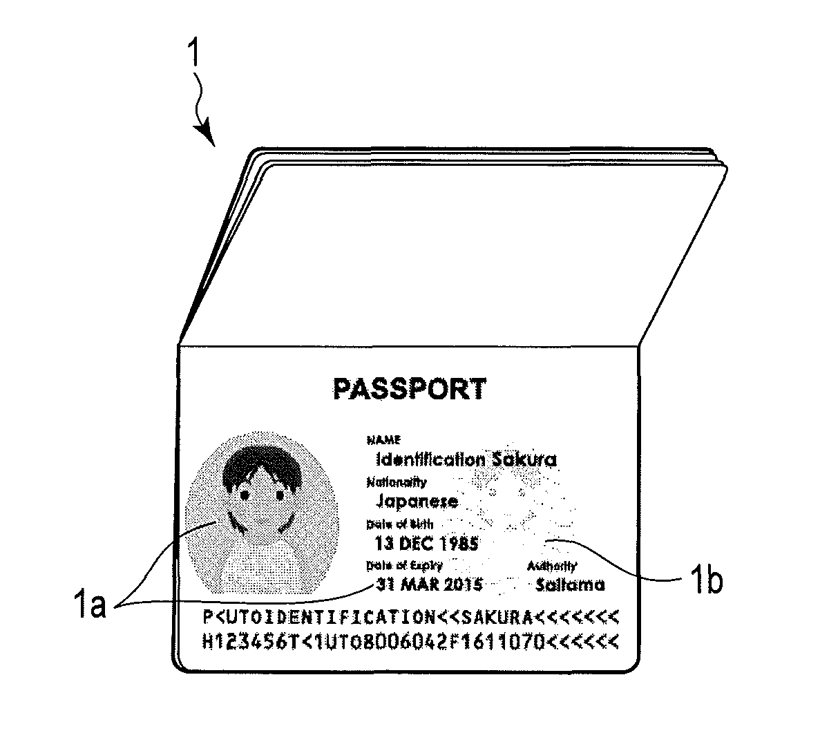
However, there is a concern that such a passport is tampered by re-attaching a photoprint.
By applying the above-described image display techniques to passports, tampering of passports becomes more difficult.
However, a face image, which is recorded by using a fluorescent material, cannot be observed unless a special light source, such as an ultraviolet lamp, is used.
In addition, although a face image, which is formed by using a pearl pigment, can be recognized by the naked eye, it is difficult to form an image with high fineness by using the pearl pigment since the grain size of the pearl pigment is large.
In addition, in a case where a face image is displayed with a simple look, it is difficult to visually determine with ease a counterfeited or tampered face image.

Method used


Image

  • Hologram transfer foil, fabrication method of image display element, image display element, and personal authentication medium
  • Hologram transfer foil, fabrication method of image display element, image display element, and personal authentication medium
  • Hologram transfer foil, fabrication method of image display element, image display element, and personal authentication medium

Examples


examples

[0101]A concrete example of the fabrication of the image display element 300 will be described below.

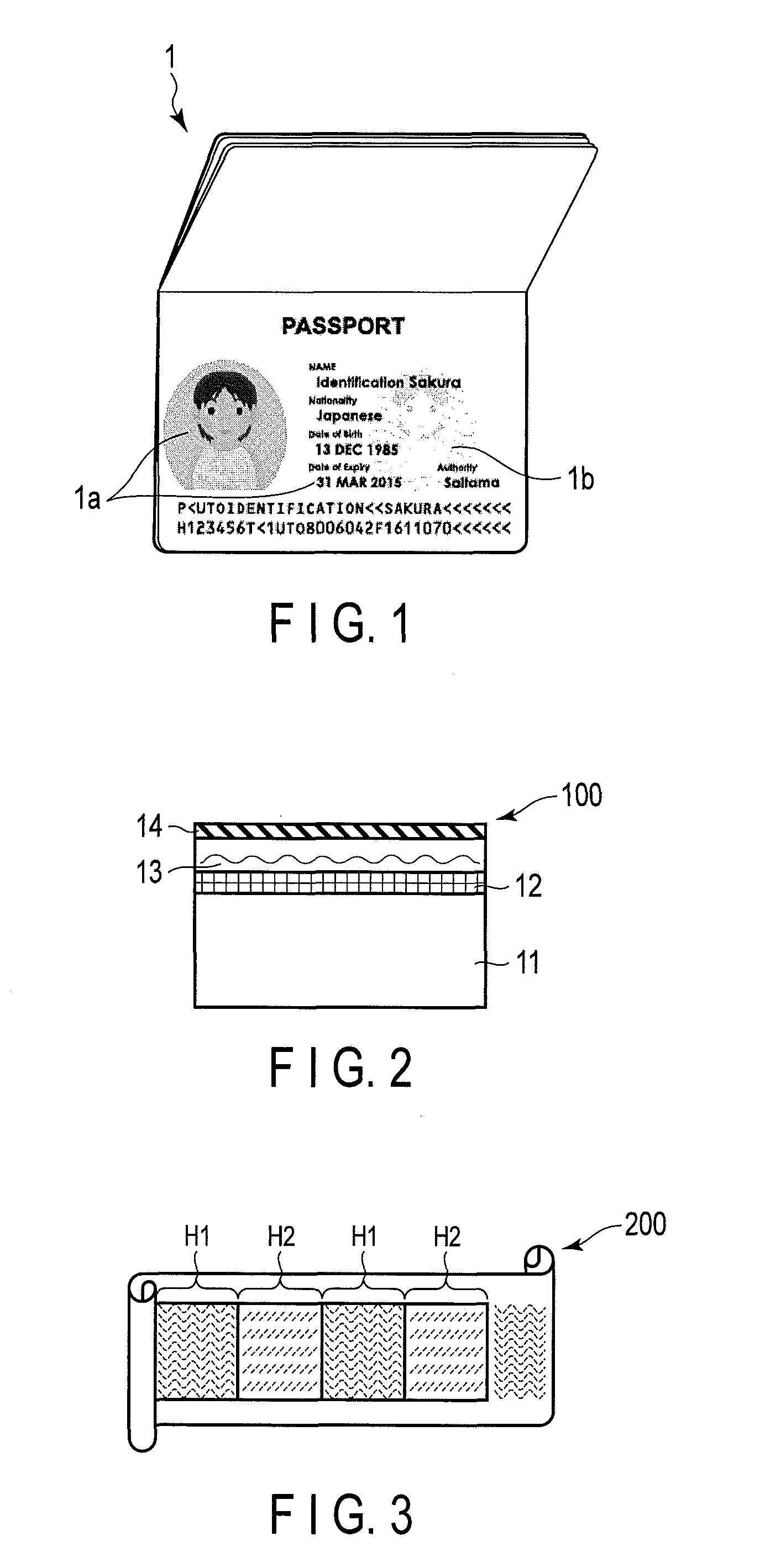
[0102]To begin with, a first hologram transfer foil (for example, the hologram transfer foil 100 shown in FIG. 2) is fabricated.

[0103]As a substrate 11, a polyethylene terephthalate film with a thickness of about 12 μm is prepared. A peeling layer 12 and a diffraction structure forming layer 13 are formed in the named order on the substrate 11 by using a gravure coater. A multilayer structure of the substrate 11, peeling layer 12 and diffraction structure forming layer 13 is dried in an oven. Incidentally, as a plate of the gravure coater, use is made of a plate on which a guilloche pattern of 175 lines / mm is applied. In addition, as the material of the peeling layer 12, an acrylic resin is used. As the material of the diffraction structure forming layer 13, acrylpolyol is used. The film thicknesses of the dried peeling layer 12 and diffraction structure forming layer 13 are about 0....


PUM


Abstract

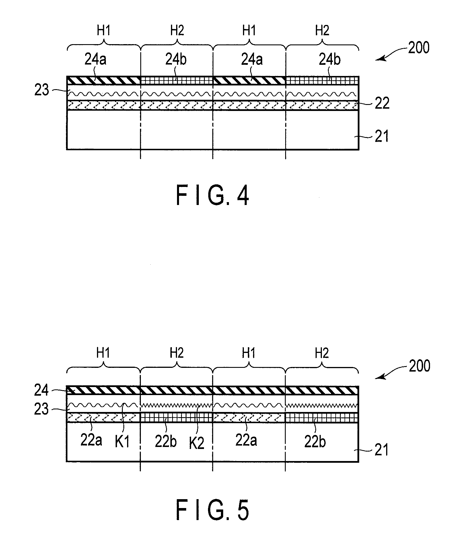
A hologram transfer foil according to an embodiment is thermally transferrable to a transfer base member. The hologram transfer foil has a structure configured such that a peeling layer, a diffraction structure forming layer and an adhesive layer are stacked on one surface of a substrate. the diffraction structure forming layer includes fine concaves and convexes of a hologram or a diffraction grating. At least one of the peeling layer and the adhesive layer includes heat-conductive hidden information in a heat-conductive hidden information possession portion.

Description

CROSS-REFERENCE TO RELATED APPLICATIONS[0001]This application is Continuation Application of PCT Application No. PCT / JP2013 / 061825, filed Apr. 23, 2013 and based upon and claiming the benefit of priority from the Japanese Patent Application No. 2012-099972, filed Apr. 25, 2012, the entire contents of all of which are incorporated herein by reference.BACKGROUND OF THE INVENTION[0002]1. Field of the Invention[0003]Embodiments described herein relate generally to a hologram transfer foil which is easy to identify and difficult to counterfeit and tamper, a fabrication method of an image display element, an image display element, and a personal authentication medium.[0004]2. Description of the Related Art[0005]In most of personal identification media such as passports or ID (identification) cards, face images are used in order that personal authentication can be visually performed. For example, in a general passport, printing paper on which a face image is printed is attached to a bookle...

Claims


Application Information

Patent Timeline
Patent Type & Authority Patents(United States)
IPC IPC(8): G03H1/00G03H1/26G03H1/02B42D25/328B42D25/00B44C1/17G03H1/04
CPCB42D25/00B42D25/328B44C1/17G03H1/0252G03H1/0256G03H1/0011G03H1/0244G03H1/265G03H2001/0016G03H2001/0027G03H2001/0497G03H2210/54G03H2240/21G03H2250/10G03H2270/23B42D25/309B42D25/455B42D25/46B42D25/24G03H1/0236
Inventor INOKUCHI, MASAMI
Owner TOPPAN PRINTING CO LTD
Learn More