Braking apparatus for vehicle with collision avoidance mechanism

a technology of collision avoidance mechanism and braking apparatus, which is applied in the direction of automatic initiation, braking system, transportation and packaging, etc., can solve the problems of lowering the mountability of the brake system in automotive vehicles, and achieve the effect of facilitating the mountability of the braking apparatus

Active Publication Date: 2017-02-07
ADVICS CO LTD
View PDF22 Cites 1 Cited by
  • Summary
  • Abstract
  • Description
  • Claims
  • Application Information

AI Technical Summary

Benefits of technology

[0008]It is therefore an object to provide a braking apparatus with a collision avoidance system which is easy to mount in a vehicle.
[0010]When it is determined that there is the risk of collision with the obstacle, the collision avoidance controller opens the first solenoid valve. This causes the hydraulic pressure of the brake fluid, as delivered from the accumulator, to move the spool valve to a location where the pressure-increasing mode is established, thereby developing the braking force in the friction braking device. Basically, emergency braking is achieved by installing the first solenoid valve to selectively exert the hydraulic pressure of the brake fluid stored in the accumulator on the spool valve, thus allowing an emergency avoidance braking system to be constructed with a minimum of equipment and facilitating the mountability of the braking apparatus in the vehicles.

Problems solved by technology

A combination of the collision avoidance system and the hydraulic booster, therefore, would result in increased number of solenoid valves, hydraulic pipes, or control mechanism making up the brake system to achieve the collision avoidance, thus leading to lowered mountability of the brake system in automotive vehicles.

Method used


Image

  • Braking apparatus for vehicle with collision avoidance mechanism
  • Braking apparatus for vehicle with collision avoidance mechanism
  • Braking apparatus for vehicle with collision avoidance mechanism

Examples


second embodiment

Frictional Brake Unit in Second Embodiment

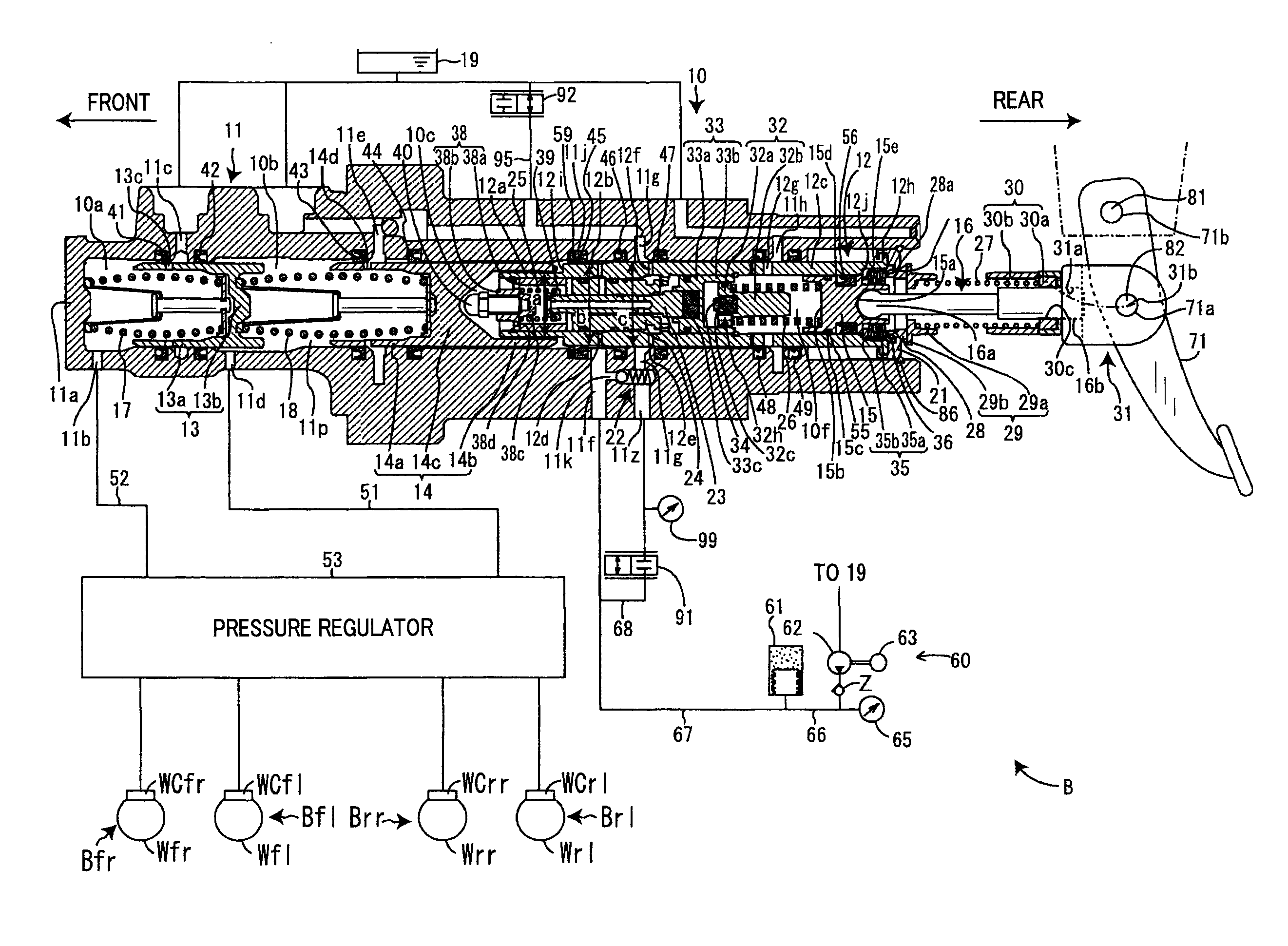
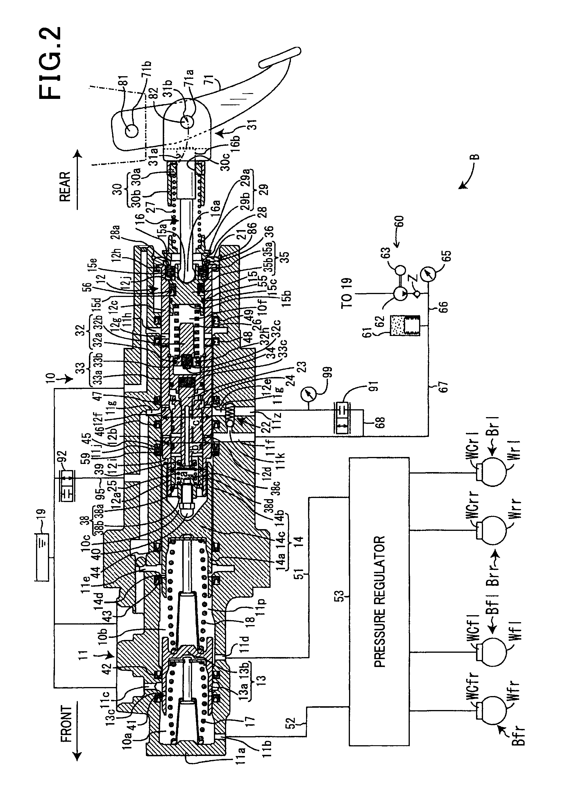
[0173]FIG. 14 illustrates a frictional brake unit B-2 (i.e., a brake system) of the second embodiment. The same reference numbers as employed in the first embodiment will refer to the same parts, and explanation thereof in detail will be omitted here.

[0174]The second solenoid valve 92 is installed in the flow path 64 which connects the reservoir 19 and the seventh port 11h. In other words, the second solenoid valve 92 is disposed in a flow path extending between the simulator chamber 10f and the reservoir 19. The first solenoid valve 91 is disposed in the flow path 69 which connects between a portion of the flow path 64 which is closer to the seventh port 11h than the second solenoid valve 92 is and the flow path 67. In other words, the first solenoid valve 91 is arranged in a flow path extending between the simulator chamber 10f and the accumulator 61.

[0175]When the collision avoidance braking mode is entered, the ECU 6 closes the second so...


PUM


Abstract

A braking apparatus for a vehicle is provided which includes a hydraulic booster to make wheels of the vehicle produce frictional braking force, a solenoid valve, and a collision avoidance controller. The solenoid valve selectively exerts the hydraulic pressure of brake fluid stored in an accumulator on a spool valve in the booster. When determining that there is a risk of a collision with an obstacle, the collision avoidance controller opens the solenoid valve to achieve emergency braking to minimize the risk of the collision. Basically, emergency braking is achieved by installing the solenoid valve to selectively exert the hydraulic pressure on the spool valve, thus allowing an emergency avoidance braking system to be constructed with a minimum of equipment and facilitating the mountability of the braking apparatus in the vehicles.

Description

CROSS REFERENCE TO RELATED DOCUMENT[0001]The present application claims the benefit of priority of Japanese Patent Application No. 2014-14194 filed on Jan. 29, 2014, the disclosure of which is incorporated herein by reference.BACKGROUND OF THE INVENTION[0002]1. Technical Field[0003]This disclosure relates generally to a braking apparatus for vehicles which works to control braking force applied to, for example, an automobile.[0004]2. Background Art[0005]Japanese Patent First Publication No. 2012-192776 has proposed a collision avoidance system which works to automatically brake a vehicle to avoid an accident with an obstacle present ahead of the vehicle when it is determined that there is a probability of collision with it.[0006]Japanese Patent First Publication No. 2011-240872 teaches a brake system for automobiles which is equipped with a brake simulator and a hydraulic booster. The brake simulator works to imitate an operation of a typical brake system, that is, make the driver o...

Claims


Application Information

Patent Timeline
Patent Type & Authority Patents(United States)
IPC IPC(8): B60T7/22B60T13/14B60T13/68B60T8/48B60T7/04B60T11/18B60T13/66
CPCB60T7/22B60T7/042B60T8/4845B60T11/18B60T13/147B60T13/662B60T13/686B60T2201/022B60T13/142
Inventor YAMASHITA, HIRONOBUYAMAGUCHI, TAKAHIROTAKEUCHI, KIYOHITOSASAKI, YASUHIROISHIMURA, JUNJISUZUKI, ATSUSHI
Owner ADVICS CO LTD
Why Eureka
Try Eureka