Use of a sky polarization sensor for absolute orientation determination in position determining systems

a technology of absolute orientation and position determining system, which is applied in the direction of optical radiation measurement, distance measurement, instruments, etc., can solve the problems of time-consuming setup procedure, inconvenient for high-adjustable positioning applications, and inability to bring the pole in the first pla

Active Publication Date: 2017-02-07
TRIMBLE INC
View PDF18 Cites 30 Cited by
  • Summary
  • Abstract
  • Description
  • Claims
  • Application Information

AI Technical Summary

Problems solved by technology

This setup procedure is time-consuming, and is a source of error if not accomplished accurately.
However this is achieved through electronic tilt sensors and magnetometers, which deliver only low accuracy measurements of roughly one degree, and so are not suitable for high accuracy positioning applications.
Again, leveling a pole requires a bubble-level indicator as in the case of a survey tripod, and takes some time to bring the pole into a vertical alignment with sufficient accuracy to meet survey requirements.
Further, there are many circumstances where the GNSS receiver cannot be located exactly at or over the target point.

Method used


Image

  • Use of a sky polarization sensor for absolute orientation determination in position determining systems
  • Use of a sky polarization sensor for absolute orientation determination in position determining systems
  • Use of a sky polarization sensor for absolute orientation determination in position determining systems

Examples


example implementation

of a Sky Polarization Sensor for Absolute Orientation Determination in Position Determining Systems

[0081]FIG. 6A-6E show various use scenarios of a device 100 in accordance with various embodiments. In FIG. 6A, device 100 comprises a tripod-mounted survey device (e.g., a theodolite or total station as described with reference to FIGS. 4A and 4B) which is disposed above a control point 601. Because device 100 can determine its absolute orientation using polarization sensor 101 and orientation determiner 104, there is no necessity to level the instrument or to backsight to another known reference point to establish the absolute orientation of device 100. In other words, device 100 can be set up at control point 601 and measurements of the relative angle and range to target 610 can be acquired. As a result, the amount of time to set up and begin collecting data using embodiments of device 100 is greatly reduced.

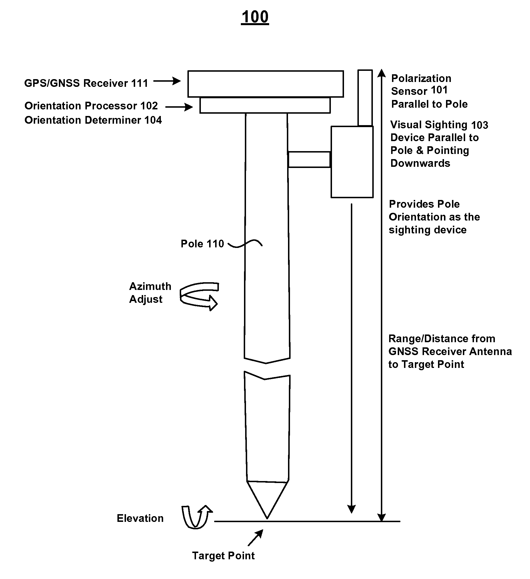
[0082]In FIG. 6B, device 100 comprises a pole (e.g., 110 of FIGS. 1B and 1C...

example vehicle

Control System and Example Vehicle Using Same

[0187]FIG. 27 is a block diagram of an example vehicle control system in accordance with various embodiments. In FIG. 27, vehicle control system 2700 comprises a polarization sensor 101 configured to capture measurements of sky polarization as discussed above. Vehicle control system 2700 further comprises GNSS receive 111 which is configured to provide location and time information. Vehicle control system 2700 further comprises an orientation determiner 104 configured to determine the orientation of components of vehicle control system such as polarization sensor 101, the location of antenna phase center of an antenna used by GNSS receiver 111, or other components such as a visual sighting device 103 which may be used as a sensor for vehicle control system 2700. In various embodiments, vehicle control system 2700 further comprises wireless link 107 which is configured to send and / or receive data with, for example, polarization reference s...


PUM


Abstract

A method for determining absolute orientation of a platform is disclosed. In one embodiment, a first sky polarization data set for a first time Ti is measured using a sky polarization sensor disposed on a platform. A second sky polarization data set is obtained at a second time Tj. A difference in orientation between the first sky polarization data set and the second sky polarization data set is determined using an orientation determiner. The difference in orientation is provided as at least one orientation parameter for the platform at time Tj. The at least one orientation parameter is used to provide a direction relative to a reference point on the platform.

Description

RELATED APPLICATIONS[0001]This application claims priority to U.S. Provisional Application Ser. No. 61 / 674,563, entitled “USE OF A SKY POLARIZATION SENSOR FOR ABSOLUTE ORIENTATION DETERMINATION IN POSITION DETERMINING SYSTEMS,” with filing date Jul. 23, 2012, by Peter Glenn France, assigned to the assignee of the present application, and hereby incorporated by reference in its entirety.BACKGROUND[0002]Position determination is required for the execution of a variety of activities. Some survey and mapping activities include determining the position of objects in the world, either near the position determination device or some distance away. Other activities include navigation or stakeout, where the coordinates of a destination is known, and the operator is guided to that destination by iteratively determining the position of a device and comparing that position with the destination coordinate. The position determination process in optical surveying typically starts from a known locat...

Claims


Application Information

Patent Timeline
Patent Type & Authority Patents(United States)
IPC IPC(8): G01B11/26G01S19/53G01C15/00G01C17/00G01J4/04G01S17/06G01S19/43G06G7/70G01S19/48G01C3/08
CPCG01B11/26G01C3/08G01C15/00G01C17/00G01J4/04G01S17/06G01S19/43G01S19/48G01S19/53G06G7/70G01S19/485
Inventor FRANCE, PETER GLEN
Owner TRIMBLE INC
Why Eureka
Try Eureka