System for treating heart valve malfunction including mitral regurgitation

a technology of positioning structure and mitral valve, which is applied in the direction of heart stimulators, prostheses, therapy, etc., can solve the problems of mitral valve remaining partially open during ventricular contraction, mitral valve regurgitation, and blood back into the left atrium, so as to facilitate the positioning of at least one, and eliminate or restrict mitral regurgitation

Active Publication Date: 2017-02-14
CORQUEST MEDICAL
View PDF478 Cites 8 Cited by
  • Summary
  • Abstract
  • Description
  • Claims
  • Application Information

AI Technical Summary

Benefits of technology

[0015]The present invention is directed to an intra-pericardial surgically introduced positioning structure that is disposed between the inner surface of the pericardium and the outer surface of the myocardium. Moreover, the positioning structure is operative to repetitively assume an expanded orientation and a contracted orientation. As such, structural and operative features of the positioning structure serve to repetitively and temporarily exert a “lifting” or “shaping” force on the exterior of the myocardium, specifically in the area of the ventricular wall supporting the tethered papillary muscle. The delivery of such a temporary and repetitive lifting or shaping force, in synchronization with the heartbeat or cardiac cycle, enable one of the mitral leaflets, typically a tethered posterior leaflet, to meet its anterior counterpart and coapt to a sufficient degree to eliminate or restrict mitral regurgitation. For purposes of clarity, the terms “lifting force” or “shaping force” or their equivalents are compatible in that the force exerted on the heart will temporarily and repetitively at least partially change the “shape” of the heart to the extent of “lifting” the left ventricular wall in a manner which facilitates a positioning of at least one of the mitral leaflets into a coapting relation with the other mitral leaflet.
[0018]Accordingly, at least one embodiment of the retaining assembly includes at least one substantially semi-rigid guide wire or like structure, having sufficient flexibility to be guided or maneuvered into a position about the ventricular wall or the large vessels of the cardiac outflow tracks, through the transfer sinus (sinus Theild). However, in at least one additional preferred embodiment the retaining assembly may include a retaining structure in the form of a net-like sack, sock or bag structure and / or configuration. Further, the net, sack, etc., is preferably formed from an open mesh material comprising a plurality of strands connected in at least partially spaced relation to one another. As such, the open mesh material of the retaining structure is dimensioned so as to at least partially overlie, enclose and / or surround the biventricular wall of the myocardium. In such a preferred position or orientation, the open mesh retaining structure will serve to dispose the expandable and contractible positioning structure in an appropriate position relative to the aforementioned ventricular wall associated with the tethered papillary muscle. In such position and as set forth above, the positioning structure will exert sufficient force, when expanded, to effectively “lift” the affected mitral leaflet into closing relation to the counterpart leaflet of the mitral valve.
[0022]In addition, the plurality of electrodes are operatively disposed in a predetermined array relative to the heart so as to facilitate the activating assembly having both “sensing” capabilities and “pacing” capabilities. As such, the sensing capabilities are operative to synchronize the expansion and contraction of the positioning structure so as to coincide with the cardiac cycle, as indicated above. Moreover, the pacing capabilities are operative to stimulate the heart into a biventricular resynchronization pacing. As used herein, the term “biventricular synchronization” is meant to include the stimulating or “pacing” of the heart in a manner that left and right ventricles expand and contract in a manner which facilitates normal or acceptable blood flow through the heart in accordance with a normal or acceptable cardiac cycle.

Problems solved by technology

A dysfunction of any of the described mitral valve apparatus can cause “mitral regurgitation”.
This abnormal leaking of blood from the left ventricle, through the mitral valve and, into the left atrium when the left ventricle contracts, results in the “regurgitation” of blood back into the left atrium.
However, when the mitral valve malfunctions, due to various cardiac diseases, the leaflets are no longer coapting resulting in the mitral valve remaining partially open during ventricular contraction.
When the mitral valve does not close hermetically during the ventricular contraction, the aforementioned back flow of blood to the atrium and the pulmonary vasculature, results in a deleterious condition.
More specifically, this condition increases the work load to the heart and may lead to heart failure.
This situation is correlated with a poor outcome for the patient, since it increases the workload to the heart, as well as it increases the left atrial and ventricular chambers volumes.
Furthermore, the existence of severe mitral regurgitation and ventricular dilation generate a vicious cycle in which MR begets more MR.
Indeed, when the ventricle increases in size the distance between the papillary muscles increases, tethering the mitral chordae and impeding their full motion up to the plane of the annulus.
This pathophysiological continuum leads to heart failure, pulmonary hypertension, atrial fibrillation and ultimately death.
Repairing ischemic mitral insufficiency poses particular problems and challenges that have been approached in different ways.
However, many of such approaches have been disappointing on the very mid-term, with most studies reporting ≧40% of failure rate only two years after the surgery.
Indeed, the scar tissue replacing the death of the myocardium during the body repair process is immobile and remains distended in systoly.
Therefore, by tethering as above-mentioned, the mobility of the entire mitral apparatus attached to it is impaired resulting in the PPM, the chordae and the leaflets being pulled “down” or away from the plane of the mitral annulus.

Method used


Image

  • System for treating heart valve malfunction including mitral regurgitation
  • System for treating heart valve malfunction including mitral regurgitation
  • System for treating heart valve malfunction including mitral regurgitation

Examples


Embodiment Construction

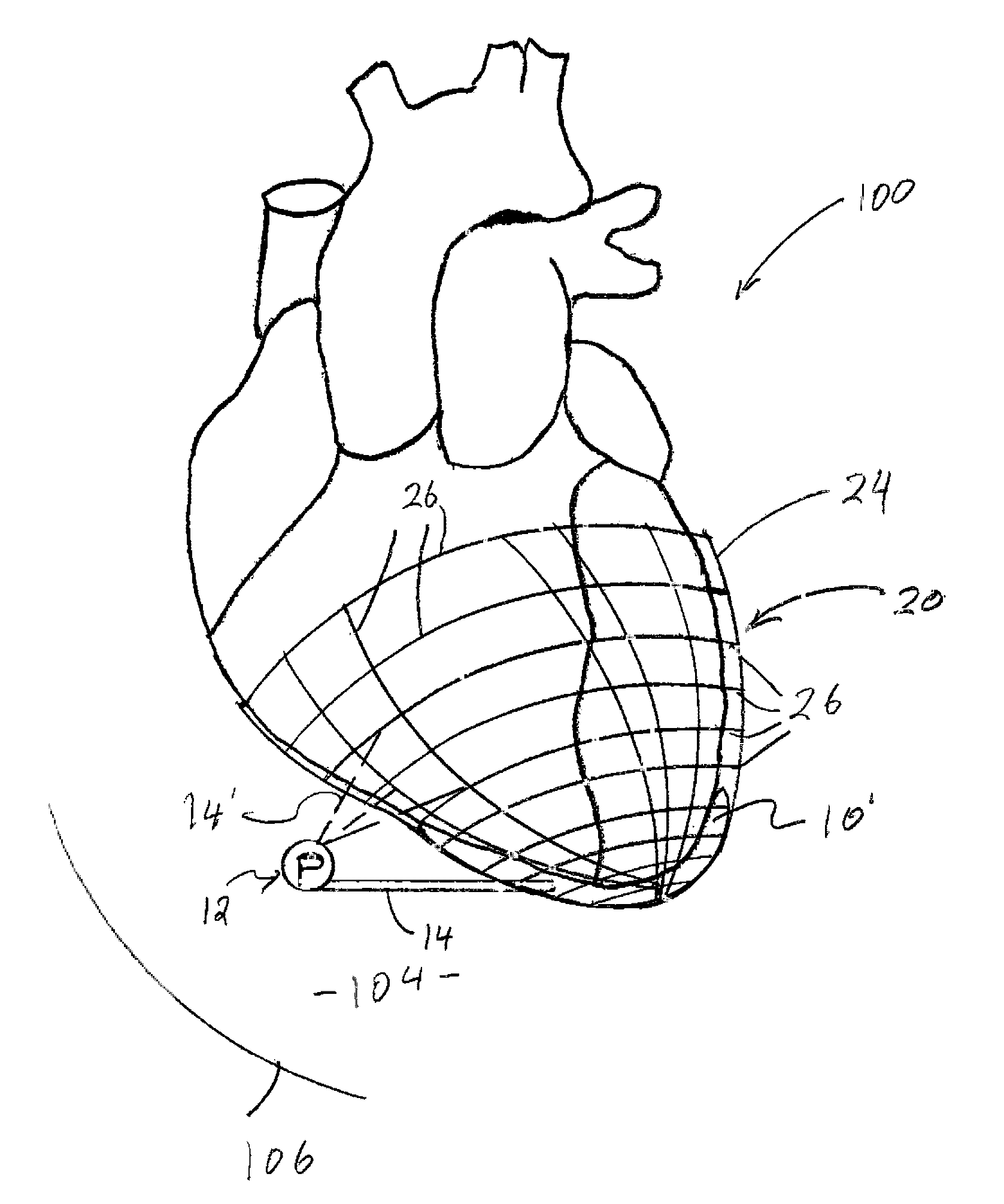
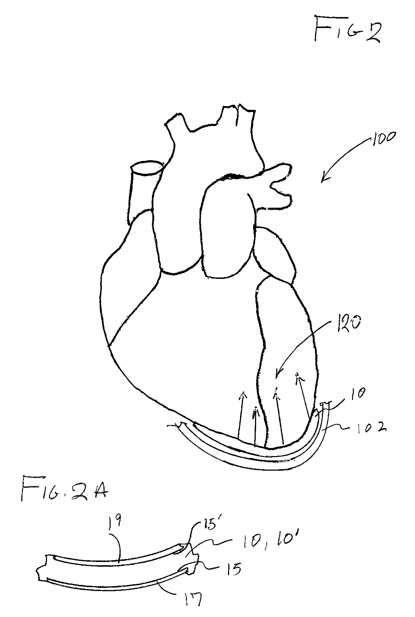
[0034]As represented in the accompanied drawings, the present invention is directed to a system for treating heart valve malfunction specifically including mitral regurgitation, wherein the various operative structural components are represented throughout FIGS. 2 through 5. For purpose of clarity a representative human heart is generally indicated as 100 and is surrounded and / or enclosed by a pericardium 102, wherein the operative and structural components of the system of the present invention are located within the interior of the chest cavity 104. In providing a clear perspective of the environment in which the system of the present invention is practiced, the outer chest wall 106, chest cavity 104, pericardium 102 and heart 100 are all represented in schematic form.

[0035]In more specific terms, the system of the present invention is directed to an intra-pericardial, surgically introduced positioning structure 10 located between the inner surface of the pericardium 102 and the o...


PUM


Abstract

A system for treating heart valve malfunction specifically including mitral regurgitation including a positioning structure operative to assume both expanded and contracted orientations and a retaining assembly positioned and structured to operatively dispose the positioning structure in moveably supporting lifting and / or positioning relation to the ventricular wall portion of the heart. The retaining assembly and the positioning structure are cooperatively disposed and structured to accomplish a shape variance of the heart upon a lifting or positioning force being exerted thereon substantially concurrent to the positioning structure being disposed in the expanded orientation. The force exerted on the heart at least partially defines a shape variance thereof to the extent of positioning of the leaflets of the mitral valve into a closed orientation which restricts mitral regurgitation.

Description

BACKGROUND OF THE INVENTION[0001]Field of the Invention[0002]The present invention is directed to an intra-pericardial surgically introduced positioning structure that is disposed and structured to repetitively assume an expanded orientation and a contracted orientation. As such, a repetitively and temporarily “lifting” or “shaping” force is exerted on the exterior of the myocardium in synchronization with the heartbeat thereby positioning the leaflets of the mitral valve to close to a sufficient degree to eliminate or restrict mitral regurgitation.[0003]Description of the Related Art[0004]As clearly disclosed in the prior art schematic representation of FIG. 1, the human heart is a four chambered pump that moves blood efficiently through the vascular system. During normal operation, blood enters the heart through the vena cava and flows into the right atrium. Thereafter, blood flows from the right atrium through the tricuspid valve and into the right ventricle. Upon contraction of ...

Claims


Application Information

Patent Timeline
Patent Type & Authority Patents(United States)
IPC IPC(8): A61F2/24A61N1/368A61N1/05A61M1/10
CPCA61N1/368A61M1/1068A61N1/0587A61N1/0597A61N1/3684A61N1/36843A61M60/289A61M60/839A61M60/191A61M60/468
Inventor DE CANNIERE, DIDIER
Owner CORQUEST MEDICAL
Why Eureka
Try Eureka