Wire harness with shield

a wire harness and shield technology, applied in the direction of insulated conductors, connection contact materials, cables, etc., can solve the problems of time-consuming wrapping tasks, wire harness bulges, and the demands for cost mitigation and weight reduction of wire harnesses cannot be met. , to achieve the effect of stable contact, weight reduction, and cost mitigation

Active Publication Date: 2017-02-14
SUMITOMO WIRING SYST LTD
View PDF4 Cites 5 Cited by
  • Summary
  • Abstract
  • Description
  • Claims
  • Application Information

AI Technical Summary

Benefits of technology

[0009]According to this configuration, in the present invention, at least a portion of electrical lines located on the outer circumferential side of the electrical line group are grounded via the ground connection member that comes into contact with the metal thin-films of this portion of the electrical lines. Accordingly, there are no cases in which the shield material is wrapped around the outside of the electrical line group, and shield grounding with a short ground line length and low impedance is possible. Accordingly, there is no bulging even if the shield section is long, and the wire harness can exhibit the required shield effects while keeping the number of parts and work hours low.
[0011]According to this configuration, the throwing power and adhesion of the metal thin-film for shielding with respect to the outer circumferential surface portion of the sheathing increases, and a fine, hard-to-peel thin metal-film for sheathing can be reliably formed in the necessary shield section.
[0013]According to this configuration, by holding the electrical line group with the holding member, the assembly of the ground connection member to the electrical line group is complete, and also the metal thin-film of the at least a portion of electrical lines can be reliably and easily brought into contact with the ground connection member.
[0015]In this case, adhesion of the connection conductor film, which functions as the ground connection member, to the holding member body is increased, and detaching is less likely to occur. Also, the connection conductor film that is not prone to detachment can be formed on the surface of the holding member body, which is light weight, comparatively flexible, and formed by resin or the like, and therefore a more stable state of contact can be ensured between the connection conductor film and the shielding metal thin-film of at least a portion of the electrical lines, weight reduction is possible, and also the connection conductor film and the metal thin-film for shielding are less likely to become damaged.
[0016]According to the present invention, a wire harness that has a shield structure that can exhibit the required shield effects, and sufficiently meet demands for both cost mitigation and weight reduction can be provided.

Problems solved by technology

However, with the former conventional wire harness in which the electrical line group is enveloped by a shield material and an exterior member for sheathing, the shield material such as braided shield material or served shield material and the exterior member for sheathing are wrapped in layers around the electrical line bundle in the routing section to be shield, and therefore the task of wrapping was time consuming.
Moreover, the wire harness bulges, and the demands for cost mitigation and weight reduction for the wire harness could not be sufficiently met.
Also, this issue becomes prominent in the case of a routing path section to be shielded over a wide range.
Also, in the case where the latter conventional wire harness, in which a metal plating layer is formed between inner and outer sheathing lawyers, is employed in a wire harness, even if many electrical lines having this shield structure are included, it was difficult for those electrical lines to contribute to the shielding of other electrical lines.
For this reason, it remains that the task of enveloping an electrical line group with a shield material in order to shield other electrical lines in a wire harness is not only consuming, but also leads to bulging of the wire harness, and demands for cost mitigation and weight reduction for the wire harness could not be sufficiently met.

Method used


Image

  • Wire harness with shield
  • Wire harness with shield
  • Wire harness with shield

Examples


first embodiment

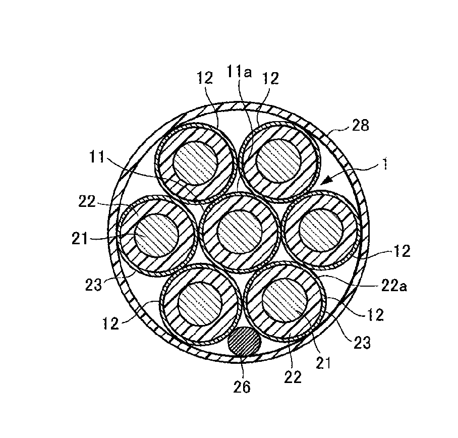
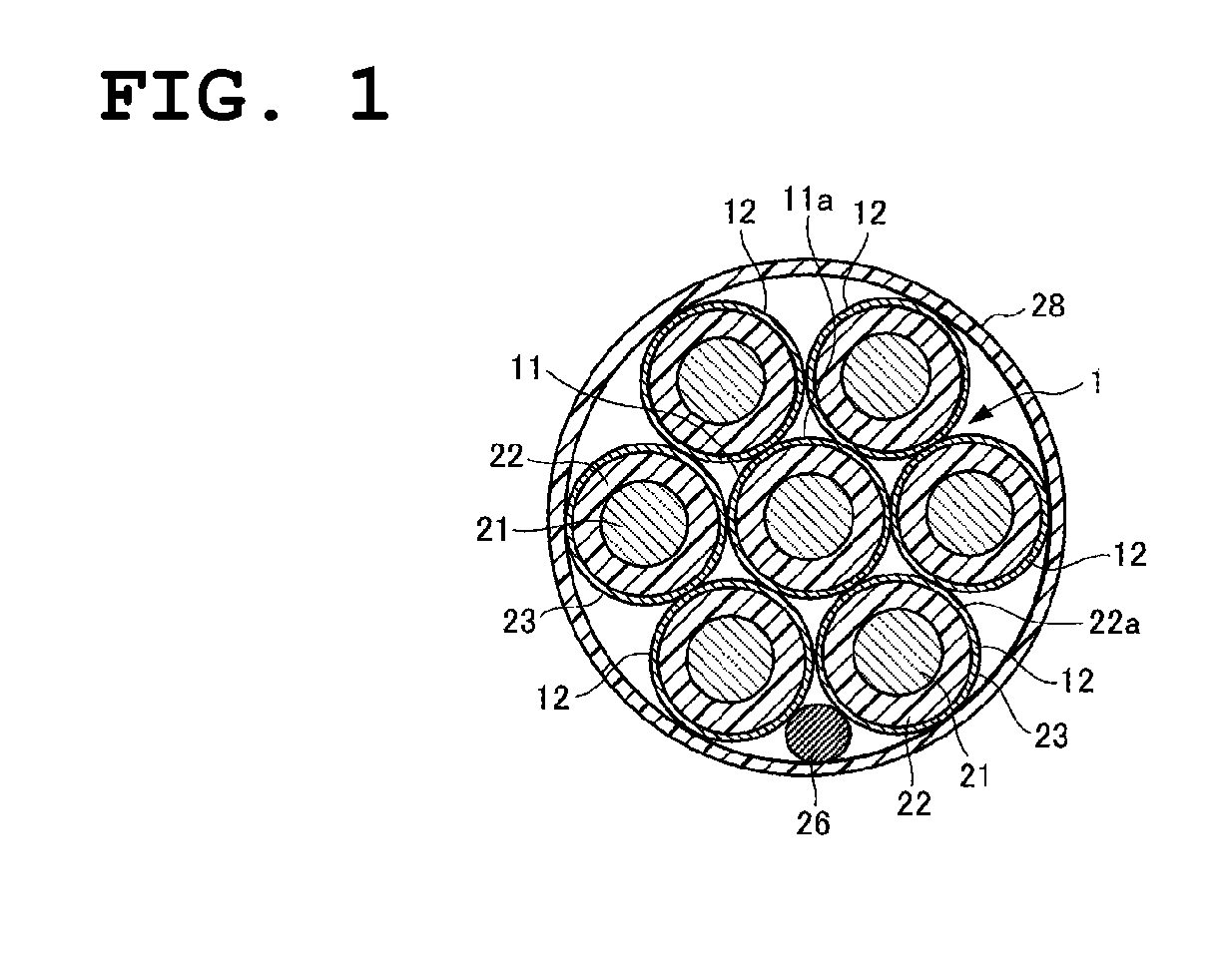
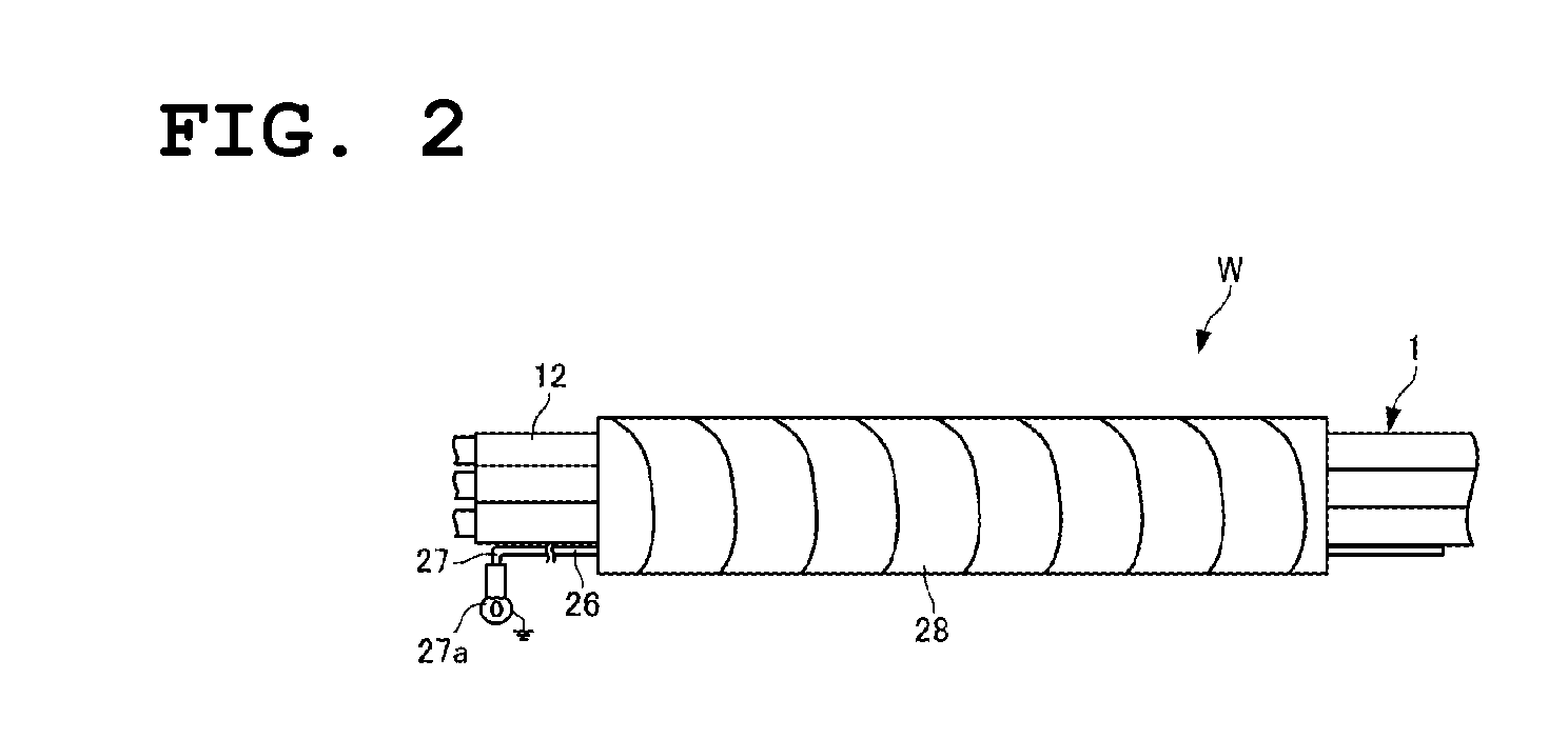
[0026]FIGS. 1 to 4 show an electrical line group 1 of a wire harness W that has an electrical line shield structure according to a first embodiment of the present invention.

[0027]Note that the wire harness W of the present embodiment is a unit in which multiple connection terminals and connectors that are not shown in the drawings, and the like, are mounted onto the electrical line group 1 that is in a bundled form, and is configured such that various types of electronic devices that are equipped in a vehicle can be connected to a power source or control equipment, for example.

[0028]The electrical line group 1 of the wire harness W has flexible properties that allow it to be routed along a predetermined routing path on a vehicle body panel that is not shown in the drawings, and a shield section that requires a shield for electrostatic shielding or the like, is provided in a midway portion of the routing path. The shield for electrostatic shielding described here includes an electros...

second embodiment

[0055]FIGS. 5 to 7 show the electrical line group 1 of the wire harness W that has an electrical line shielding structure according to a second embodiment of the present embodiment. Note that in the following embodiments, the configuration itself of the electrical lines 11 and 12 of the electrical line group 1 are similar to the first embodiment, and the aspects of the ground connection member and the holding member are different from those of the first embodiment. Accordingly, configurations that are similar to or the same as those in the first embodiment will be described using the reference numerals of the corresponding constituent elements shown in FIGS. 1 to 4, and the points that are different from the first embodiment are described below.

[0056]As shown in FIG. 5, in the present embodiment, a ground connection member 41 in the form of a cable tie that can bundle the electrical lines 11 and 12 of the electrical line group is provided. In other words, instead of the drain wire 2...

third embodiment

[0067]FIGS. 8A and 8B show the electrical line group 1 of the wire harness W that has an electrical line shielding structure according to a third embodiment of the present embodiment.

[0068]As shown in FIG. 8A, the electrical line group 1 is protected and surrounded from the outer circumferential by a holding member 48 having a predetermined length.

[0069]As shown in FIG. 8B, the holding member 48 includes a heat shrink tube body 51 (holding member body) that functions as a holding member that holds the electrical lines 11 and 12 in a bundled manner, and a connection conductor film 53 that has been formed so as to attach to at least the inner circumferential surface of the heat shrink tube body 51. Also, the connection conductor film 53 is constituted by a vapor deposition film that is formed by RF ion plating.

[0070]The drain line 26 comes into contact with the metal thin-film 23 of any of the electrical lines 12, the electrical lines 11 and 12 and the drain wire 26 are in contact wit...


PUM

PropertyMeasurementUnit
outer diameteraaaaaaaaaa
thicknessaaaaaaaaaa
thicknessaaaaaaaaaa

Abstract

A wire harness having a shield structure that can exhibit a required shield effect and sufficiently meet demands for cost mitigation and weight reduction is provided. The wire harness is provided with an electrical line group that is held in a bundled manner, in which at least a portion of electrical lines that are positioned on the outer circumferential side of the electrical line group each have a metal thin-film for shielding as the outermost layer, the metal thin-film being formed so as to attach to an outer circumferential surface portion of a sheathing that surrounds a conductor of the electrical line, and a drain wire or another ground connection member that is grounded and comes into contact with the metal thin-films of the electrical lines.

Description

TECHNICAL FIELD[0001]The present invention relates to a wire harness, and in particular a wire harness that has a structure that shields an electrical line group of the same.BACKGROUND ART[0002]Conventionally, in the case of shielding (electrostatic shielding and / or electromagnetic shielding) an electrical line group of a wire harness in a predetermined routing section, a shield structure has often implemented in which the electrical line group in the section to be shielded is enveloped with a shield material such as a braided shield material, a served shield material, or an aluminum foil shield material, and then enclosed with an exterior member sheathing that envelopes the same from the outside (e.g. see JP H10-125138A and JP 2009-93934A).[0003]Also, as a shield structure integrated with electrical lines, there is known to be a shield-including cable structure provided with a shield layer on the outer circumferential surface of an insulating layer that surrounds a conductor, and a...

Claims


Application Information

Patent Timeline
Patent Type & Authority Patents(United States)
IPC IPC(8): H01B7/00B60R16/02H01B11/10H02G15/18H01R4/18H01R4/64
CPCB60R16/0215H01B7/0045H01B11/1058H01R4/185H01R4/646H02G15/1806
Inventor WAKABAYASHI, MASATAKAFUKUDA, MINORU
Owner SUMITOMO WIRING SYST LTD
Why Eureka
Try Eureka