Transmission for a motor vehicle
a multi-speed transmission and motor vehicle technology, applied in mechanical equipment, transportation and packaging, gearing, etc., can solve the problems of high hydraulic loss, difficult access to shift elements, and hydraulically actuated internal shift elements such as multi-disk clutches or brakes, so as to increase the flexibility of the transmission with respect to its use in various vehicles.
- Summary
- Abstract
- Description
- Claims
- Application Information
AI Technical Summary
Benefits of technology
Problems solved by technology
Method used
Image
Examples
first embodiment
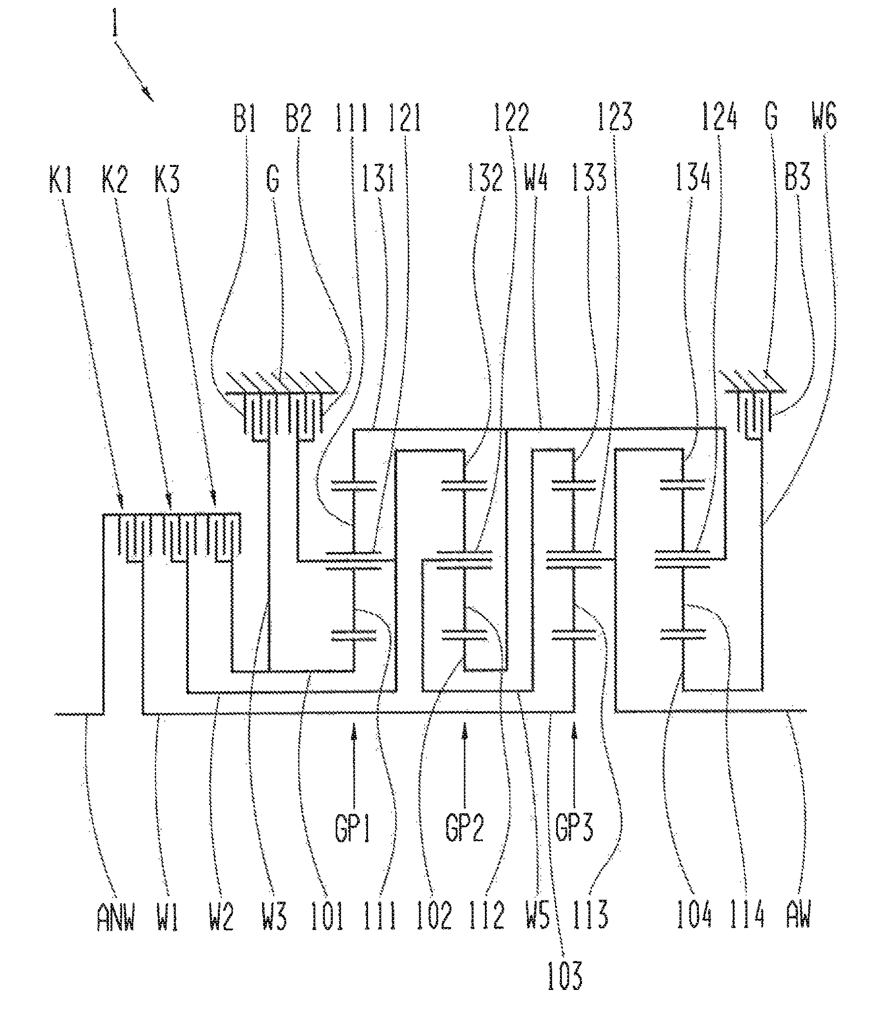
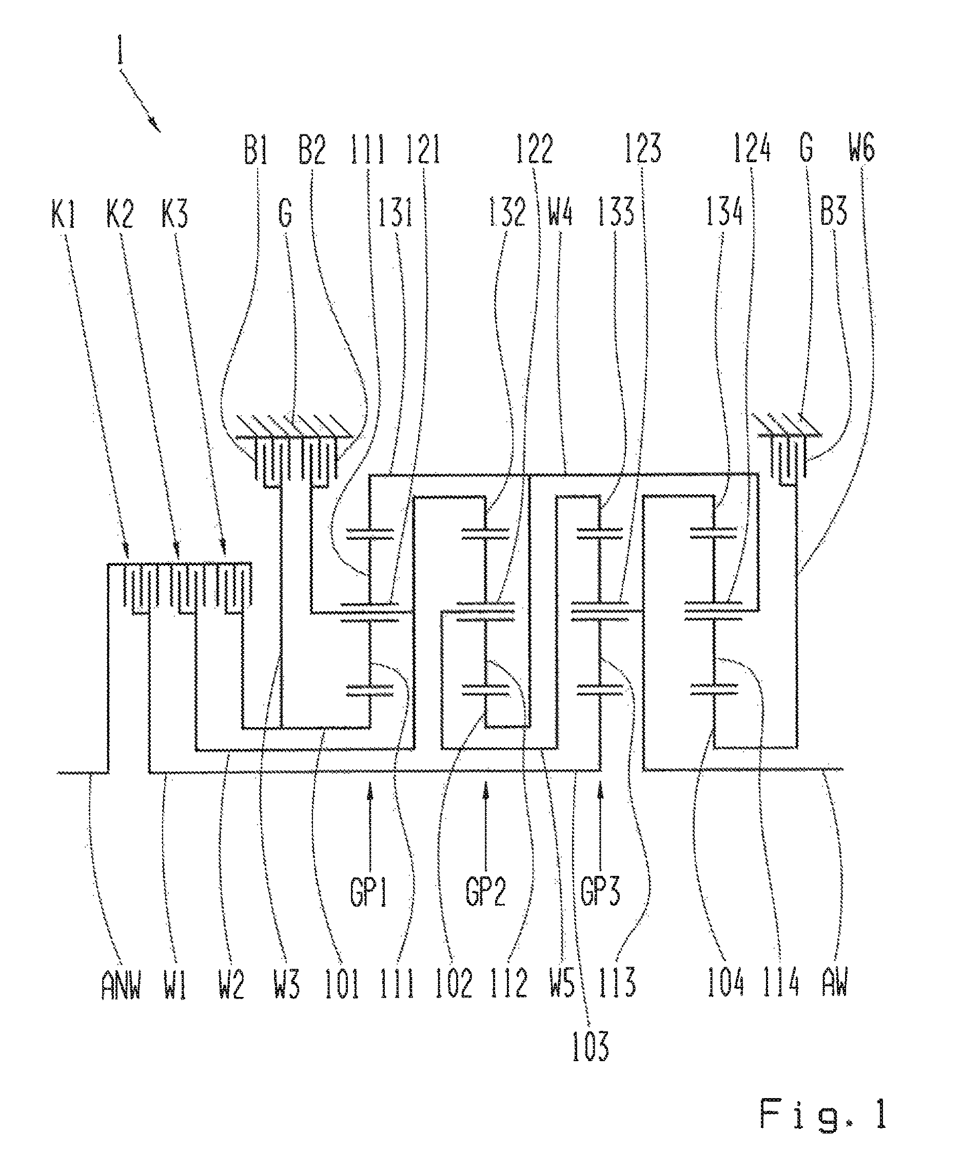
[0063]FIG. 1 shows a transmission in accordance with the present invention.
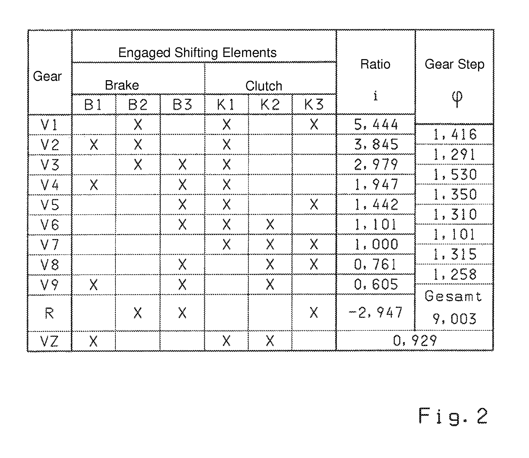
[0064]In FIG. 1, reference sign 1 shows a multi-speed transmission. The multi-speed transmission 1 features six shift elements in the form of three clutches K1, K2, K3 and three brakes B1, B2, B3. By means of the three clutches K1, K2, K3, the drive side is coupled with or connected to the output side of the transmission for the transfer of power and torque through the shafts and / or the planetary gear sets. For this purpose, the first clutch K1, the second clutch K2 and the third clutch K3 are connected to the drive shaft ANW on the drive side. The first clutch K1 is also connected to a first shaft W1, such that, when actuated, the first clutch K1 transfers power and torque from the drive shaft ANW to the first shaft W1. This correspondingly applies for the second clutch K2 and the third clutch K3. Upon locking the second clutch K2, power and torque are transferred from the drive shaft ANW to the second shaft...
second embodiment
[0080]FIG. 3 shows a transmission in accordance with the present invention.
[0081]FIG. 3 shows a transmission 1 in accordance with FIG. 1. In FIG. 3, four alternative positions A, B, C and D for the first clutch K1 can be viewed, with which the first clutch K1 can be arranged in a manner effectively equal to the position in accordance with FIG. 1.
[0082]The first alternative position A for the first clutch K1 is located between the bar 123 of the third planetary gear set GP3 and the section of the output shaft AW that is connected to the ring gear 134 of the fourth planetary gear set GP4.
[0083]The second alternative position B for the first clutch K1 is located between the bar 122 of the second planetary gear set GP2 and the ring gear 133 of the third planetary gear set GP3 on the fifth shaft W5.
[0084]The third alternative position C for the first clutch K1 is located on the fourth shaft W4 between the sun gear 102 of the second planetary gear set GP2 and the section of the fourth sha...
third embodiment
[0086]FIG. 4 shows a transmission in accordance with the present invention.
[0087]FIG. 4 shows a transmission 1 in accordance with FIG. 1. In FIG. 4, two alternative position E and F for the third brake B3 can be viewed, with which the third brake B3 can be arranged in a manner effectively equal to the position in accordance with FIG. 1.
[0088]The first alternative position E for the third brake B3 is located on the fourth shaft W4 between the bar 124 of the fourth planetary gear set GP4 and the section of the fourth shaft W4 that connects the sun gear 102 of the second planetary gear set GP2 to the ring gear 131 of the first planetary gear set GP1.
[0089]The second alternative position F for the third brake B3 is located between the ring gear 134 of the fourth planetary gear set GP4 on the output shaft AW and the section of the output shaft AW that is connected to the bar 123 of the third planetary gear set GP3. The brake B3 acts on the alternative positions E and F like a (fourth) cl...
PUM
 Abstract
Description
Claims
Application Information
 - R&D
- Intellectual Property
- Life Sciences
- Materials
- Tech Scout
- Unparalleled Data Quality
- Higher Quality Content
- 60% Fewer Hallucinations
Browse by: Latest US Patents, China's latest patents, Technical Efficacy Thesaurus, Application Domain, Technology Topic, Popular Technical Reports.
© 2025 PatSnap. All rights reserved.Legal|Privacy policy|Modern Slavery Act Transparency Statement|Sitemap|About US| Contact US: help@patsnap.com


