
Systems approach to interference cancellation

a technology of interference cancellation and system approach, applied in the field of systems and methods for interference cancellation, can solve the problem of not knowing the interference prior to the interference, and achieve the effect of reducing the probability of interferen

Active Publication Date: 2017-02-14
BASCOM HUNTER TECH +1
View PDF1 Cites 69 Cited by
  • Summary
  • Abstract
  • Description
  • Claims
  • Application Information

AI Technical Summary

Benefits of technology

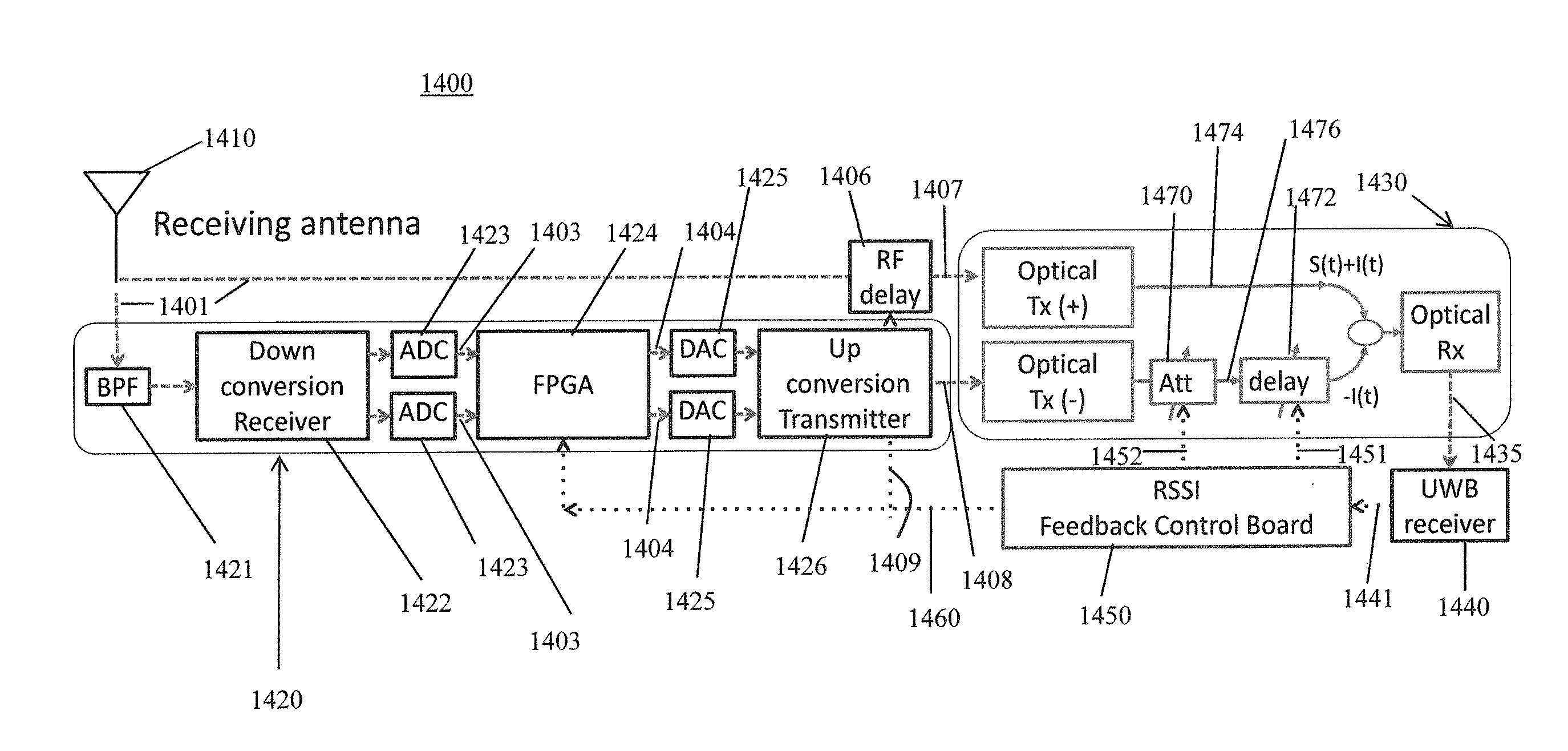
The present invention is an interference cancellation system that can optically cancel out interference components from signals received through a receiver. The system includes an interference estimation module that receives the signal and outputs an interference component, an optical interference cancellation module that receives the interference component and the signal, and removes the interference component from the signal. The system can be used in various applications such as communication systems, radar systems, and electronic warfare systems. The technical effects of the invention include improved signal quality, reduced interference, and improved performance of electronic systems.

Problems solved by technology

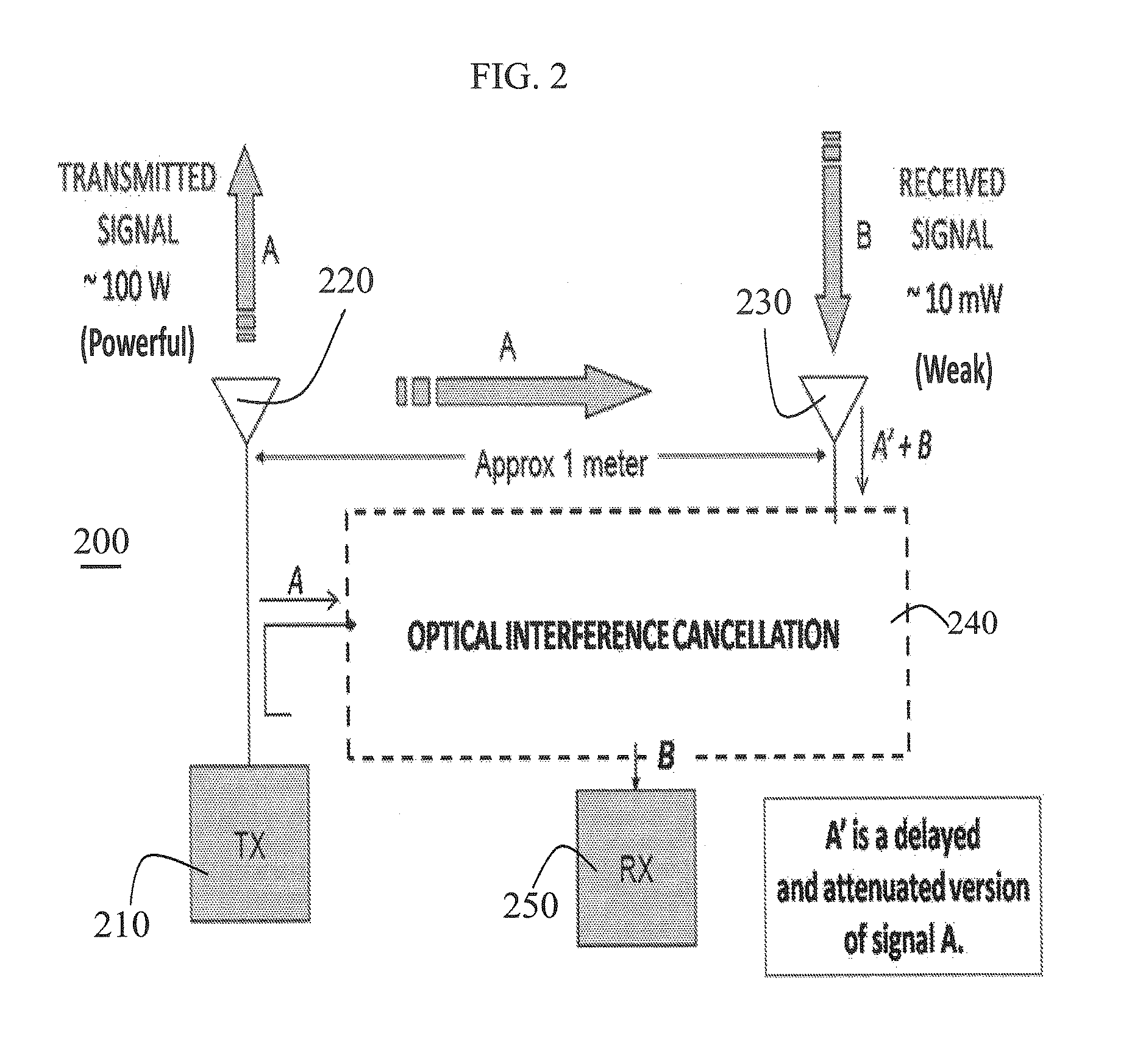
If a transmitter and receiver are co-located, this can cause significant difficulties because the transmitted signal can interfere with the desired received signal and in some cases may overpower the received signal such that it is buried under the locally transmitted signal.
Moreover, in the case of the remote interference, no prior knowledge of the interference is assumed.

Method used


Image

  • Systems approach to interference cancellation
  • Systems approach to interference cancellation
  • Systems approach to interference cancellation

Examples


Embodiment Construction

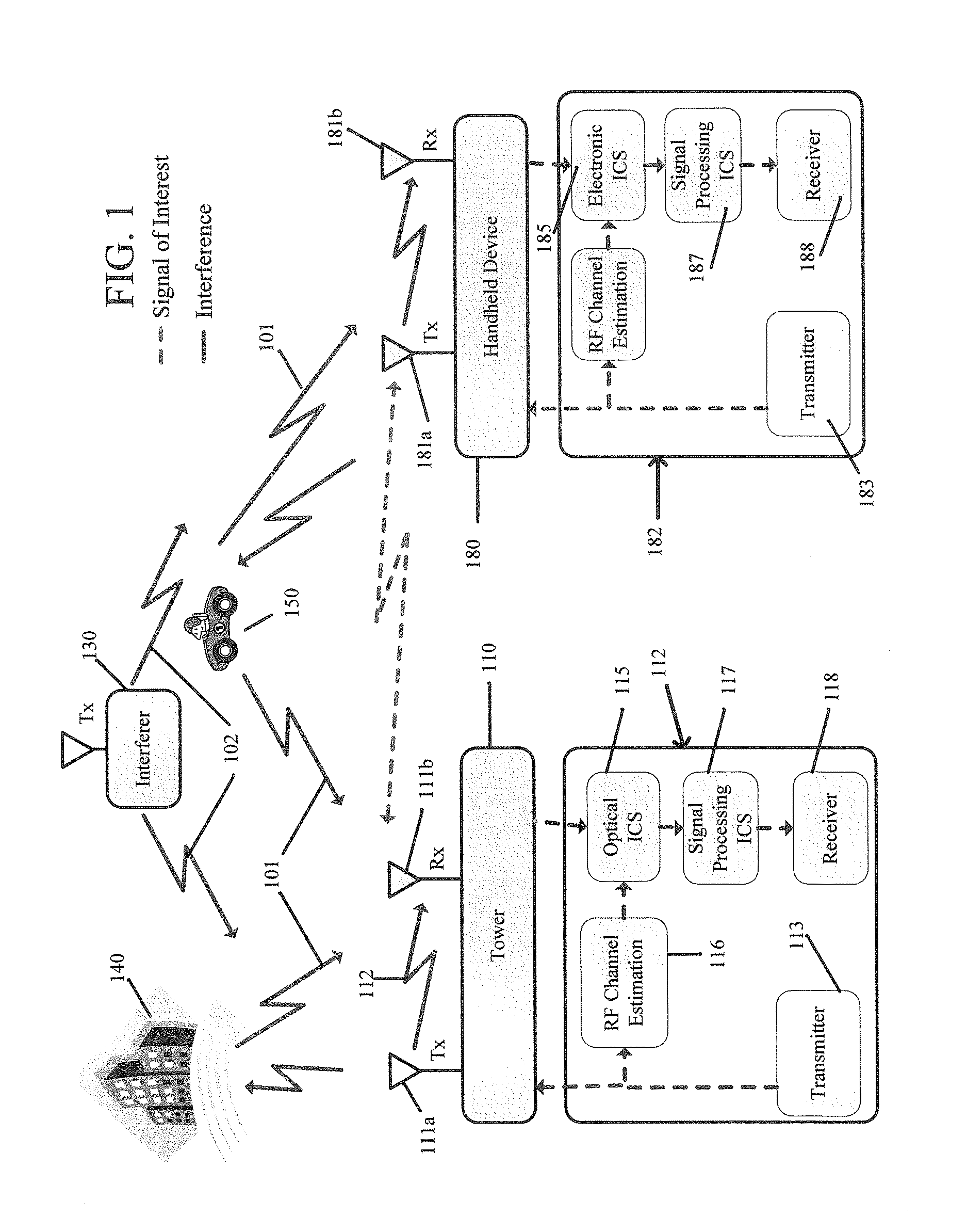
[0045]The present invention employs a systems approach to radio frequency (RF) interference cancellation that employs wideband remote interference cancellation using optical processing as well as digital and electronic cancellation methods. Interference is one of the key limitations of RF equipment. Removing interference is a very challenging problem because it can be generated from multiple sources with characteristics that change rapidly and in unpredictable ways. Whereas traditional approaches based on channel spacing and filtering are robust, they result in an inefficient use of the RF spectrum. Additionally, with traditional approaches, unexpected interference such as multi-path interference and remote interference can result in abrupt disruption of the communication link.

[0046]In the scenario shown in FIG. 1, a tower 110 and handheld device 180 are attempting to communicate with each other over a large distance. There are several sources of interference, including: transmissio...


PUM


Abstract

Disclosed is a system and method of combining optical interference cancellation with other methods of interference cancellation, including electronic cancellation, digital filtering, and beam steering algorithms, to remove co-located interference, remote interference of an unknown origin, and multipath interference components created by reflections of signals both known and unknown.

Description

CROSS-REFERENCE TO RELATED APPLICATIONS[0001]The present application claims the benefit of the filing date of U.S. Provisional Patent Application Ser. No. 61 / 198,336 (Suarez et al.) filed on Nov. 5, 2008 and U.S. Provisional Patent Application Ser. No. 61 / 488,521 filed on May 20, 2011, which are incorporated herein by reference as if set forth in full below.[0002]This application is a continuation-in-part of and claims priority to U.S. Nonprovisional application Ser. No. 12 / 613,512, filed on Nov. 5, 2009, and U.S. Nonprovisional patent application Ser. No. 13 / 399,327, filed on Feb. 17, 2012, which are incorporated herein by reference as if set forth in full below.STATEMENT REGARDING FEDERALLY SPONSORED RESEARCH OR DEVELOPMENT[0003]This invention was made with government support under Prime Contract W911NF-07-D-000I (Subcontract TCN: 08-004) awarded by the Department of the Army. This invention was also made with government support under Subaward #96183NBS68 from Booz Allen Hamilton,...

Claims


Application Information

Patent Timeline
Patent Type & Authority Patents(United States)
IPC IPC(8): H04B10/61
CPCH04B10/61G02F2/002H04B1/525G02F1/0121G02F1/225
Inventor SUAREZ, JOHNPRUCNAL, PAUL R.DENG, YANHUAMCCANDLESS, ANDREW
Owner BASCOM HUNTER TECH
Learn More