Interference cancellation system

Active Publication Date: 2006-02-23
ASSIA SPE LLC CO THE CORP TRUST CO
View PDF12 Cites 70 Cited by
  • Summary
  • Abstract
  • Description
  • Claims
  • Application Information

AI Technical Summary

Benefits of technology

[0016] Further details and advantages of the invention are provided in the following Detailed Description and the associated Figures.
[0017] The present invention will be readily understood by the following detailed description in conjunction with the accompanying drawings, wherein like reference numerals designate like structural elements, and in which:
[0018]FIG. 1 is a diagram of a typical DSL plant.
[0019]FIG. 2 is a schematic diagram showing a generic DSL deployment in which embodiments of the present invention can be used.
[0020]FIG. 3 is a schematic block diagram showing the relevant portions of a DSL modem operating in its receiver mode and implementing one or more methods, systems and / or other embodiments of the present invention.
[0021]FIG. 4 is a schematic block diagram showing the relevant portions of a DSL modem operating with multiple DSL lines / loops coupled to the mode and implementing one or more methods, systems and / or other embodiments of the present invention.
[0022]FIG. 5A is an illustration of the plots of the power spectral density of a line and the noise(s) affecting that line's data signals received by a DSL modem.
[0022]FIG. 5A is an illustration of the plots of the power spectral density of a line and the noise(s) affecting that line's data signals received by a DSL modem.
[0024]FIG. 6 is a schematic diagram of one implementation of multiple telephone lines or loops coupled to a modem that can be used in connection with embodiments of the present invention.
[0025]FIG. 7 is a flow diagram illustrating a method according to one embodiment of the present invention for removing RF interference from signals received by a modem.

Problems solved by technology

The interference may include RF interference, such as AM radio interference, crosstalk, impulse noise and other types of man-made electronic radiation and / or interference from various sources.

Method used


Image

  • Interference cancellation system
  • Interference cancellation system
  • Interference cancellation system

Examples


Embodiment Construction

[0027] The following detailed description of the invention will refer to one or more embodiments of the invention, but is not limited to such embodiments. Rather, the detailed description is intended only to be illustrative. Those skilled in the art will readily appreciate that the detailed description given herein with respect to the Figures is provided for explanatory purposes as the invention extends beyond these limited illustrative and exemplary embodiments.

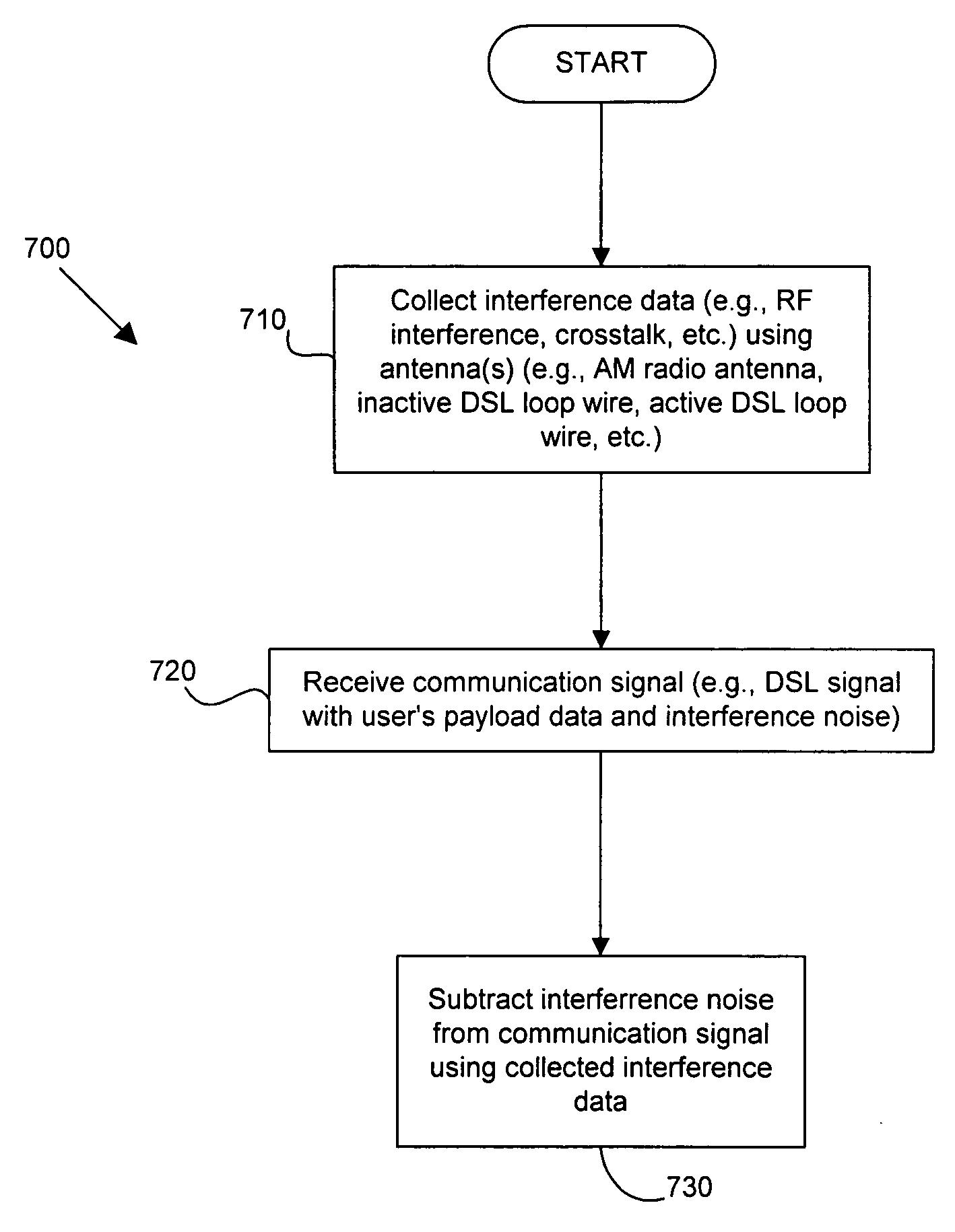
[0028] Embodiments of the present invention provide a modem, or other communication device having data signals susceptible to noise from RF and / or other interference sources (including, for example, impulse noise, crosstalk and other man-made electronic radiation), that uses an antenna (or other structure functioning like an antenna) to obtain data relating to RF and / or other interference present in the environment in which the modem and / or any unshielded or poorly shielded portion(s) of the DSL loop operate. In some embodi...


PUM


Abstract

A DSL or other communication system includes a modem or other communication device having at least one antenna that is configured to collect interference data relating to interference noise affecting communication signals being received by the communication device. The interference may include RF interference, such as AM radio interference, crosstalk and other types of interference from various sources. The interference data collected by the antenna is used by an interference canceller to remove and / or cancel some or all of the interference affecting received signals. In some embodiments of the present invention, more than one antenna may be used, wherein each antenna can collect interference data pertaining to a single source of interference noise. Where a modem or other communication device is coupled to multiple telephone lines, only one of which is being used as the active DSL line, wires in the remaining telephone lines or loops can be used as antennas. Moreover, the antenna may be an antenna, per se, such as a compact AM radio antenna or any other suitable structure or device for collecting the type(s) of interference affecting signals received by the communication device.

Description

CROSS-REFERENCE TO RELATED APPLICATIONS [0001] This application is related to U.S. Ser. No. 10 / 808,771, entitled “HIGH SPEED MULTIPLE LOOP DSL SYSTEM” and filed Mar. 25, 2004, the disclosure of which is incorporated herein by reference in its entirety for all purposes.STATEMENT REGARDING FEDERALLY SPONSORED RESEARCH OR DEVELOPMENT [0002] Not applicable. REFERENCE TO SEQUENCE LISTING, A TABLE, OR A COMPUTER PROGRAM LISTING COMPACT DISK APPENDIX [0003] Not applicable. BACKGROUND OF THE INVENTION [0004] 1. Field of the Invention [0005] This invention relates generally to methods, systems and apparatus for managing digital communications systems. More specifically, this invention relates to the use of a functional antenna in connection with a DSL modem or the like to reduce the deleterious effects of RF interference, including AM radio noise, on DSL and / or other data signals. [0006] 2. Description of Related Art [0007] Digital subscriber line (DSL) technologies provide potentially large...

Claims


Application Information

Patent Timeline
Patent Type & Authority Applications(United States)
IPC IPC(8): H04B1/38
CPCH04B1/126H04B3/32H04M3/34H04L27/2647H04M3/304H04L25/10
Inventor CIOFFI, JOHN M.
Owner ASSIA SPE LLC CO THE CORP TRUST CO
Why Eureka
Try Eureka