Mechanical face seal with a reverse trapezoidal face pattern

a mechanical face and trapezoidal technology, applied in the direction of engine seals, mechanical apparatus, engine components, etc., can solve the problems of uni-directional patterns only being effective, no longer operating in the opposite direction during shaft rotation, and leakag

Active Publication Date: 2017-02-21
FLOWSERVE MANAGEMENT CO
View PDF38 Cites 10 Cited by
  • Summary
  • Abstract
  • Description
  • Claims
  • Application Information

AI Technical Summary

Benefits of technology

[0015]The reverse trapezoidal shape of the groove pattern causes incoming gas from the high pressure side of the seal face to be drawn in and preferentially directed into the angled portion of the groove along the side edges, creating a pumping action. Since the wider circumferential edge is spaced radially from the short circumferential edge, the side edges angle away from the short circumferential edge and create a corner like area to which the incoming gas flows and then exits to the seal face. Due to the angle of the side edges, the reverse trapezoidal shape impedes recirculation of the fluid back to the high pressure side, which recirculation normally occurs in a conventional trapezoid face pattern. By reducing radial recirculation back to the high pressure side, the reverse trapezoidal face pattern generates improved lift and film stiffness while reducing fluid recirculation.
[0016]The sinusoidal shape is provided with a radially varying depth amplitude and acts to increase compression of the gas as it travels in the groove, while also allowing some recirculation effect at the high pressure boundary that helps to discourage possibly damaging debris and contamination from getting between the seal faces. The combined effect of the reverse trapezoid shape and sinusoidal profile is to increase the incoming flow of gas into the grooves and increase the compression on that gas, resulting in increased hydrodynamic lift and film stiffness. Modeling of the fluid dynamics in this pattern design has shown a significant increase in film stiffness at equivalent gap values with the reverse trapezoidal shaped pattern versus other bidirectional patterns such as a conventional trapezoid face pattern, spiral pattern, and a sinusoidal wave pattern.
[0017]In another aspect of the invention, the reverse trapezoidal face pattern may also be provided as the primary face pattern on a dry gas seal in combination with a secondary face pattern which results in an improved ability of the faces to operate with a controlled gap under normal pressure conditions as well as when the pressure direction across the seal face is reversed. This combined pattern employs the following features:
[0021]The objective of this aspect of the invention is to provide an improved shallow groove pattern for bidirectional operation having an improved face pattern geometry that permits the seal to maintain lift both in the normal and reversed pressure directions for the seal. This allows the seal to always have a controlled lift between the seal faces regardless of pressure direction, and prevents damage from contact. This feature enables the seal to contain and survive pressure reversal conditions with a return to operation as a lift off gas seal after such an event.

Problems solved by technology

However, due to asperities in the seal faces, some leakage may occur.
However, uni-directional patterns are only effective when the shaft rotates in one direction, but no longer operate during shaft rotation in the opposite direction.
The disadvantage of uni-directional patterns is that they run with hard contact between the seal faces in events of reverse rotation, which often occurs in installations due to reversed flow of liquid through the pump.
This upset can be caused either by a loss of the supply of barrier fluid pressure to the seal's barrier cavity, or by an increase in the pressure of the pumped fluid.
The shallow groove features of typical lift-off face seals do not properly create lift with a pressure reversal condition, resulting in face contact.
Due to the relatively wide radial width of lift-off seal faces, significant heat generation results.
This can lead to wear and damage of the seal faces, which will then prevent the seal from returning to normal operation as a lift-off seal due to damage to the shallow grooves.

Method used


Image

  • Mechanical face seal with a reverse trapezoidal face pattern
  • Mechanical face seal with a reverse trapezoidal face pattern
  • Mechanical face seal with a reverse trapezoidal face pattern

Examples


Embodiment Construction

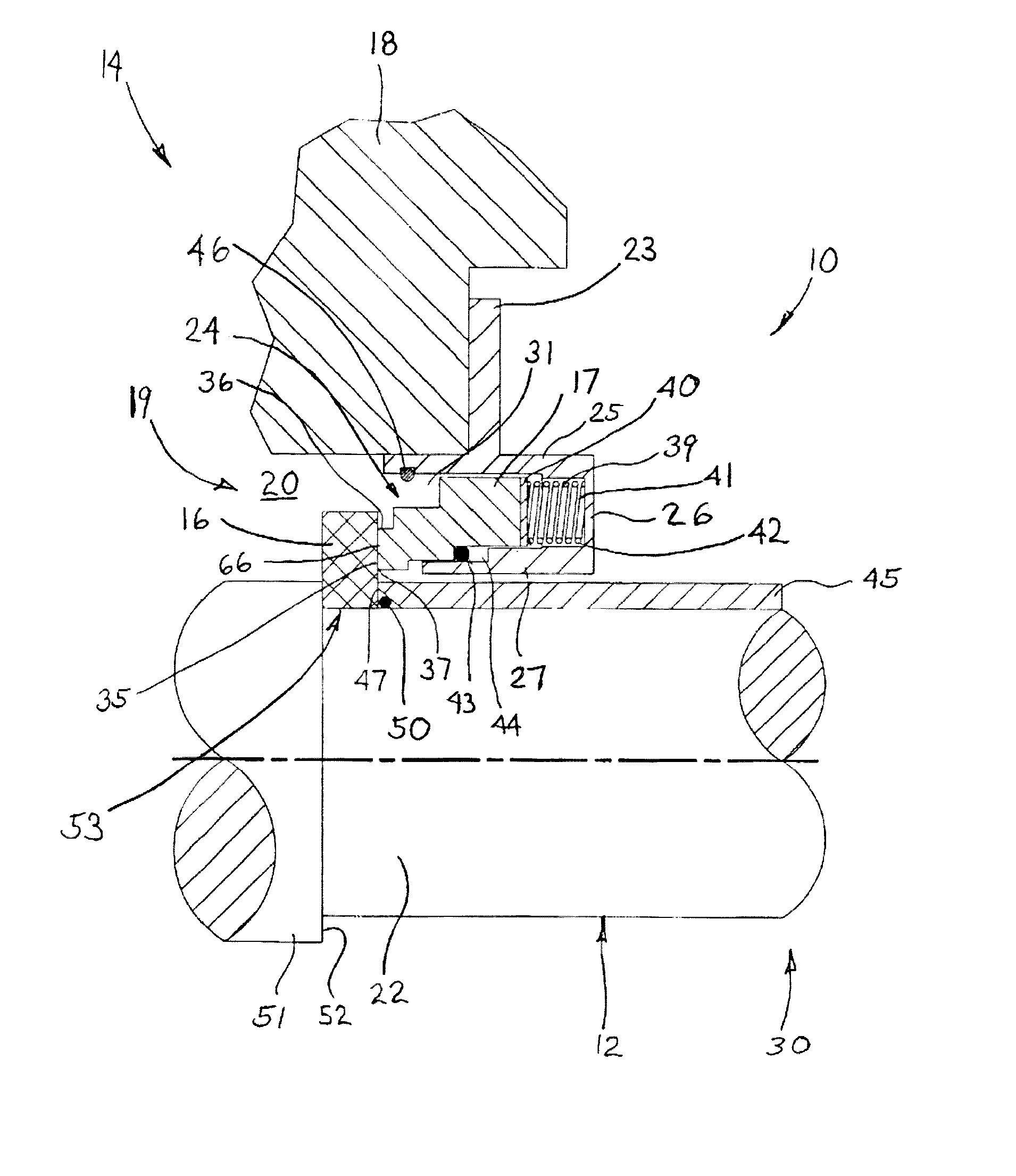
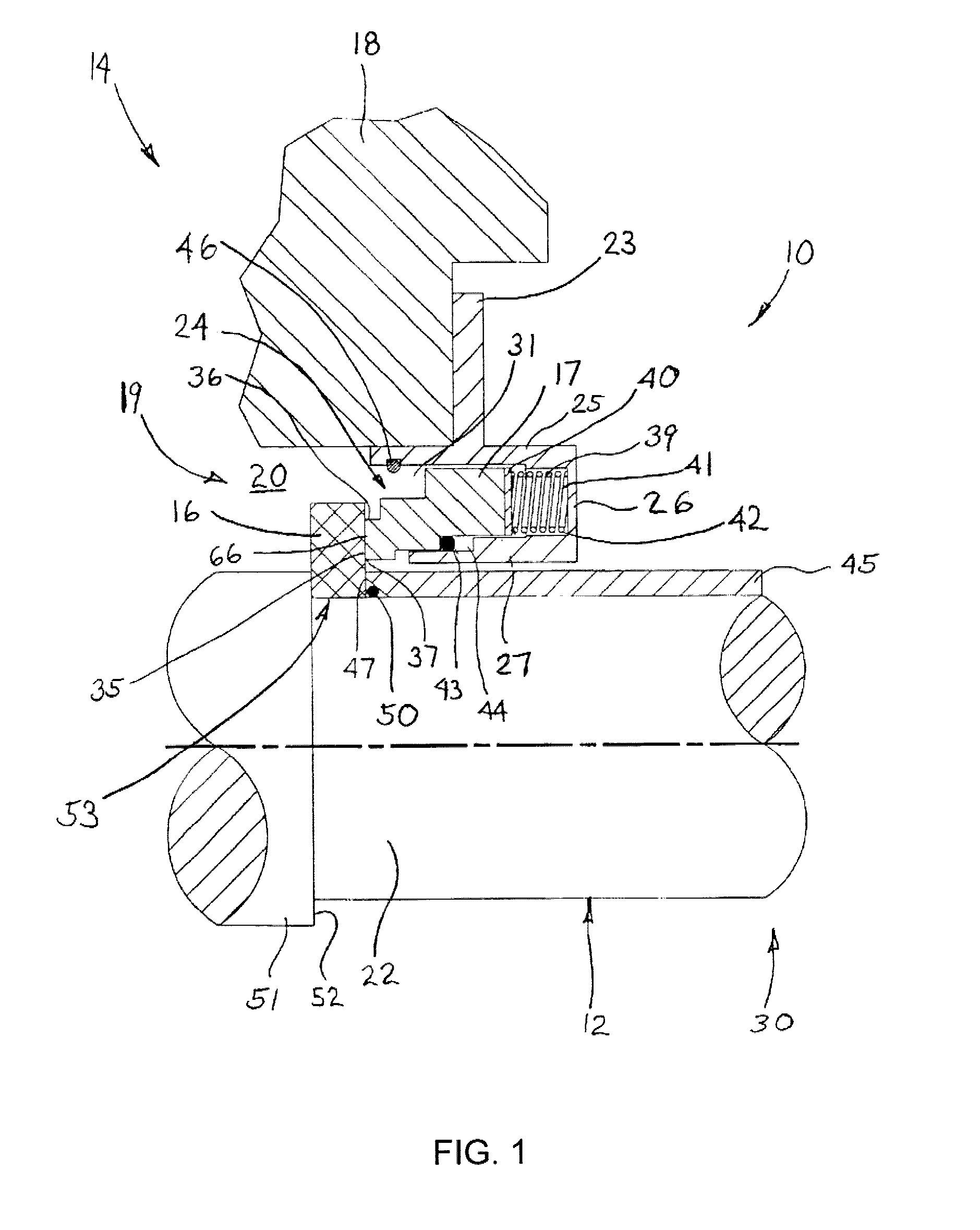
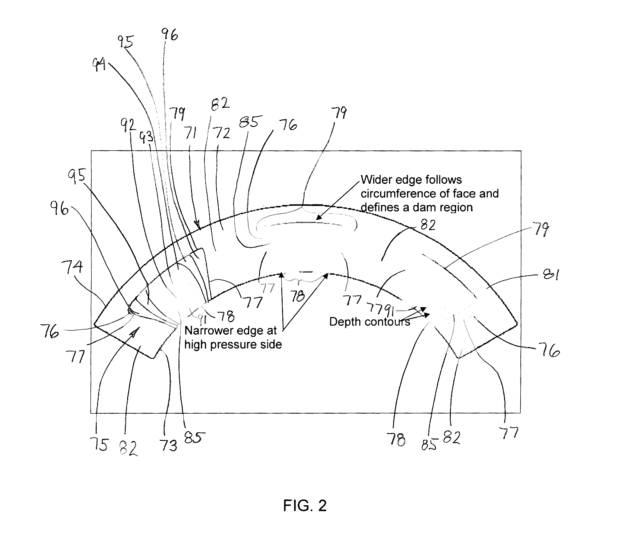
[0043]Referring to FIG. 1, a mechanical face seal 10 is illustrated mounted on the rotatable shaft 12 of a machine 14. The exemplary mechanical seal 10 includes a pair of concentric seal rings 16 and 17 which respectively operate as a rotor and a stator and effectively prevent fluid leakage along the shaft 12. Either of the seal rings 16 and 17 and most preferably, the seal ring, such as a silicon carbide ring, mating with a carbon ring is provided with a reverse trapezoidal face pattern to provide improved performance. As will be described in greater detail hereinafter, the reverse trapezoidal face pattern incorporates a sinusoidal or similarly shaped depth profile wherein the trapezoid shape is arranged with the narrower edge located on one of the ring diameters so as to communicate with the high pressure side of the seal 10, and the wider edge of the face pattern forms a circumferential dam region towards the low pressure side of the seal 10.

[0044]It should be understood that FIG...


PUM


Abstract

An improved mechanical face seal is provided which includes a pair of relatively rotatable seal rings having opposing seal faces. At least one of the seal faces includes a reverse trapezoidal face pattern having a sine wave depth profile wherein individual face features are circumferentially spaced over the seal face. The reverse trapezoidal face pattern serves to generate a hydrodynamic lift which provides a stable separation of the seal faces that permits formation of a fluid film between the seal faces. The individual trapezoidal grooves have a sinusoidal or similarly shaped depth profile wherein the trapezoid shape is arranged with the narrower edge communicating with the high pressure side of the seal, and the wider edge forms a circumferential dam region towards the low pressure side of the seal. Alternatively, the reverse trapezoidal face pattern may also be provided as a primary face pattern on a dry gas seal in combination with a secondary face pattern wherein the faces operate with a controlled gap under normal pressure conditions as well as when the pressure direction across the seal face is reversed.

Description

CROSS REFERENCE TO RELATED APPLICATIONS[0001]This application asserts priority from provisional application 61 / 755,644, filed on Jan. 23, 2013, which is incorporated herein by reference.FIELD OF THE INVENTION[0002]The invention relates to a mechanical seal arrangement, which includes a hydrodynamic face pattern, and more particularly relates to a seal face having a reverse trapezoidal face pattern providing improved hydrodynamic film stiffness in a bidirectional pattern.BACKGROUND OF THE INVENTION[0003]Mechanical face seals are used on various types of machines and equipment, such as pumps, compressors and gear boxes, which have rotating shafts and a sealing chamber adjacent the shaft wherein a fluid in the sealing chamber is prevented from leaking along the shaft. Such mechanical seals include a pair of adjacent seal rings having opposing seal faces which define a sealing region therebetween. One of these seal rings typically is mounted on the shaft so as to rotate therewith while ...

Claims


Application Information

Patent Timeline
Patent Type & Authority Patents(United States)
IPC IPC(8): F16J15/34
CPCF16J15/3428F16J15/3412
Inventor FERRIS, JASONJACOBS, LARRYGRAY, CHRISTOPHER
Owner FLOWSERVE MANAGEMENT CO
Why Eureka
Try Eureka