Method for determining a closed trajectory by means of a laser and a laser light sensor and apparatus for determining a closed trajectory curve

a laser light sensor and closed trajectory technology, applied in the direction of optical conversion of sensor output, measurement devices, instruments, etc., can solve the problems of insufficient accuracy, unusable vibration, and inability to use inclinometers, etc., to achieve the effect of precise accuracy in recording or determining the trajectory curv

Active Publication Date: 2017-02-21
PRUTECHNIK DIETER BUSCH AG
View PDF17 Cites 0 Cited by
  • Summary
  • Abstract
  • Description
  • Claims
  • Application Information

AI Technical Summary

Benefits of technology

[0033]It is provided in step E of the method according to the invention that the X coordinates and Y coordinates of at least three positions of the laser light spot or of at least three different positions of the laser light spot on the field of view are recorded by the laser light sensor. Especially preferably, the X coordinates and Y coordinates of substantially more positions, which the laser light spot assumes on the field of view during the rotation in step D, can also be determined. The number of positions can thus be, for example, even ten or twenty or more than ten or twenty, so that the determination of the closed trajectory curve can be based on a large number of positions of the laser light spot, this being associated with a very precise accuracy in recording or determining the trajectory curve, which can be determined in known way, for example, by curve fitting to the recorded X coordinates and Y coordinates.
[0034]The predetermined value of the angle of rotation according to step F of the method according to the invention is preferably zero degrees, this entailing the advantage that it is possible to measure the angle of rotation (compare also step G) in a simple and practical manner from this predetermined angle of rotation, serving as a kind of initial angle value or reference angle value of the angle of rotation. Obviously, any other value of the angle of rotation can be assigned to the first temporally recorded X coordinate and the first temporally recorded Y coordinate. The predetermined value of the angle of rotation can be defined or set at will so as to measure the angle of rotation starting from it as a kind of fixed reference.
[0039]In this case, it may be especially preferred also to record the X coordinates and Y coordinates of substantially more than sixteen positions that the laser light spot assumes on the field of view during the rotation in step D. Thus, the number of positions can be, for example, also ten or twenty or thirty more than ten or twenty or thirty, so that the closed trajectory curve can be based on a very large number of positions of the laser light spot, this entailing a very precise accuracy in recording or determining the trajectory curve, which can be determined in a known way, for example, by curve fitting to the recorded X coordinates and Y coordinates.

Problems solved by technology

Such misalignments, that is, deviations from the situation in which the axes of rotation or central axes of shafts that are connected to each other via the coupling are aligned, often lead to undesired vibrations during operation of the apparatus having the two shafts.
For the determination of any existing misalignment of essentially vertically aligned shafts, an inclinometer cannot be used or cannot be used with sufficient accuracy owing to the principle of measurement.

Method used


Image

  • Method for determining a closed trajectory by means of a laser and a laser light sensor and apparatus for determining a closed trajectory curve
  • Method for determining a closed trajectory by means of a laser and a laser light sensor and apparatus for determining a closed trajectory curve
  • Method for determining a closed trajectory by means of a laser and a laser light sensor and apparatus for determining a closed trajectory curve

Examples


Embodiment Construction

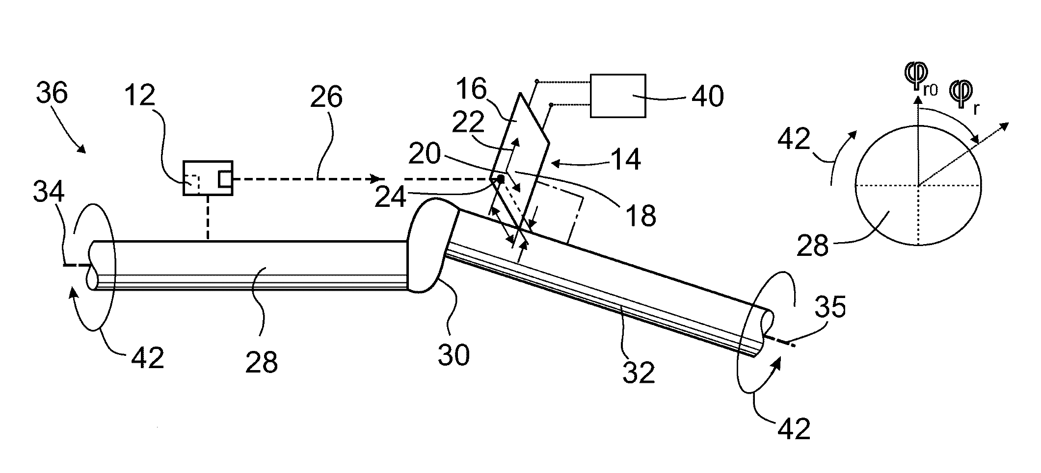
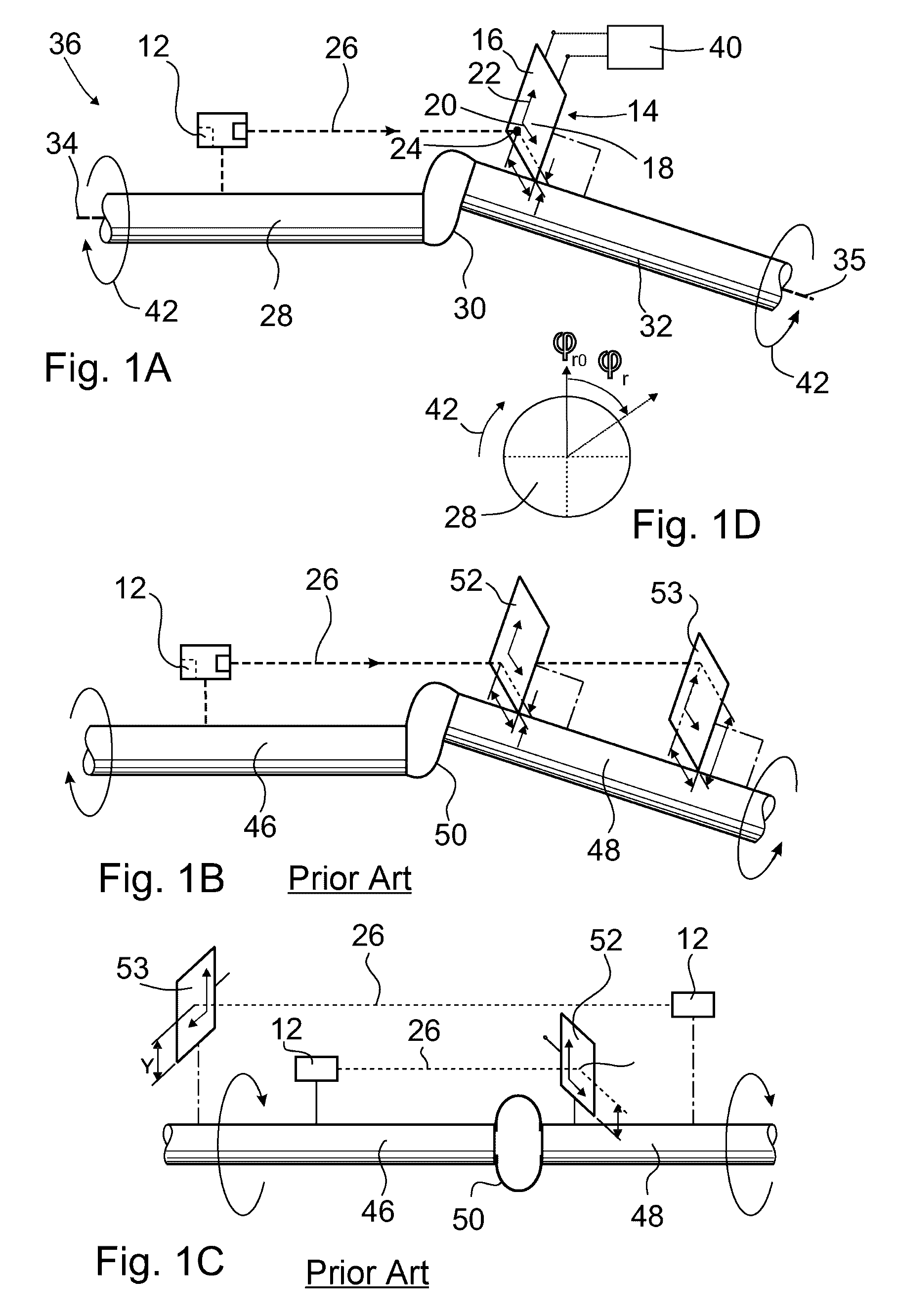
[0074]The apparatus 36 according to FIG. 1A for determining a closed trajectory curve comprises a laser 12, a laser light sensor 14 having a flat field of view 16, and an analysis unit 40.

[0075]The field of view 16 has a coordinate system 18 with an X coordinate axis 20 and a Y coordinate axis 22 that is at a right angle to the X coordinate axis 20.

[0076]The laser light sensor 14 is set up so as to record the X coordinate and Y coordinate of the position of the laser light spot 24 on the field of view 16 of the laser light beam 26 that can be generated by the laser 12 and impinges on the field of view 16.

[0077]The laser 12 can be linked to a first shaft 28 in a rotationally fixed manner, said shaft being connected to a second shaft 32 via a coupling 30, so that a rotation of the first shaft 28 can be transmitted to the second shaft 32 and vice versa.

[0078]The field of view 16 can be linked to the second shaft 32 in a rotationally fixed manner in such a way that the Y coordinate axis...


PUM


Abstract

The invention relates to a method for determining a closed trajectory curve (10) by a laser (12) and a laser light sensor (14) having a flat field of view (16), which includes the steps A to G, as well as an apparatus (36) for determining a closed trajectory curve (10).

Description

BACKGROUND OF THE INVENTION[0001]The present invention relates to a method for determining a closed trajectory curve by means of a laser and a laser light sensor having a flat field of view as well as an apparatus for determining a closed trajectory curve.[0002]Methods and apparatuses of the kind mentioned in the introduction are used, in particular, for apparatuses and methods by means of which any existing misalignment of two shafts that are connected to each other by a coupling can be determined. Such misalignments, that is, deviations from the situation in which the axes of rotation or central axes of shafts that are connected to each other via the coupling are aligned, often lead to undesired vibrations during operation of the apparatus having the two shafts.[0003]Methods and apparatuses for determining misalignment are known, for example, from DE 195 06 471 A1, DE 102 36 555 A1, DE 101 42 462 A1, DE 101 38 831 A1, and DE 39 11 307 A1.[0004]Generally known from DE 199 49 834 A1...

Claims


Application Information

Patent Timeline
Patent Type & Authority Patents(United States)
IPC IPC(8): G01B21/24G01D5/34
CPCG01D5/34G01B21/24
Inventor LOCOGE, PASCALZOCKE, CHRISTINE
Owner PRUTECHNIK DIETER BUSCH AG
Why Eureka
Try Eureka