Method for verifying the relative position of bone structures

a relative position and bone structure technology, applied in the field of bone structure relative position verification, can solve the problems of obstructive devices and presupposing damage to bone structures, and achieve the effect of low burden on patients and cost-effectiveness

Active Publication Date: 2017-02-21
BRAINLAB
View PDF9 Cites 6 Cited by
  • Summary
  • Abstract
  • Description
  • Claims
  • Application Information

AI Technical Summary

Benefits of technology

[0005]It is therefore the object of the present invention to provide a method for verifying the relative position of at least two bone structures which is quick, cost-effective and as little a burden on the patient as possible.
[0012]The three-dimensional dataset is preferably recorded pre-operatively. It is therefore possible to obtain and segment the three-dimensional dataset, which may be complicated, without time restrictions. The three-dimensional dataset is for example obtained by computer tomography (CT) or magnetic resonance tomography (MRT).

Problems solved by technology

However, this is time-consuming, and the device necessary for it is obstructive in the operating environment.
This presupposes damage to the bone structure and requires an additional or enlarged opening in the body, through which a marker device can pass.

Method used


Image

  • Method for verifying the relative position of bone structures
  • Method for verifying the relative position of bone structures
  • Method for verifying the relative position of bone structures

Examples


Embodiment Construction

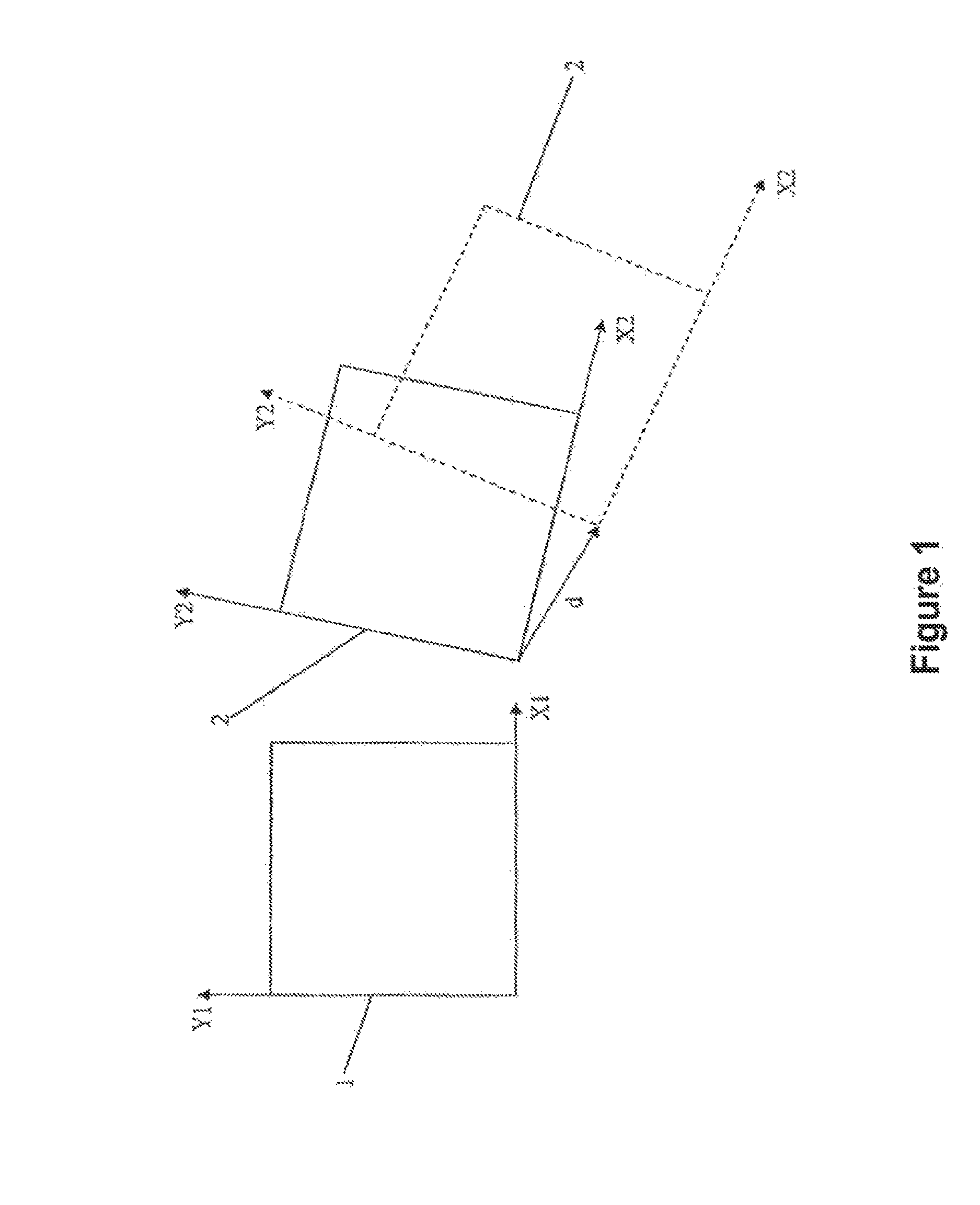
[0029]FIG. 1 schematically shows two bone structures 1 and 2, wherein a two-dimensional representation has been chosen in order to illustrate the basic principle of the method. The bone structures 1 and 2 are shown as rectangles, wherein the bone structure 1 serves as the reference. The representation of the bone structure 2 in a continuous line shows it in a first position which has been ascertained by means of a computer tomograph. The reference frame assigned to the bone structure 1 is a Cartesian coordinate system comprising the axes X1 and Y1; the reference frame assigned to the bone structure 2 is a Cartesian coordinate system comprising the axes X2 and Y2. A three-dimensional dataset has been generated with the aid of the computer tomograph and then segmented into two segments. The first segment represents the bone structure 1, and the second segment represents the bone structure 2. The segments serve as a template for subsequently locating the actual relative position of the...


PUM


Abstract

A method for verifying the position of at least two bone structures relative to each other, comprising the method steps of: recording a three-dimensional dataset which represents the bone structures; segmenting the three-dimensional dataset into segments, wherein each segment represents a bone structure and the segments exhibit a known relative position in the three-dimensional dataset; changing the virtual relative position of the segments, such that the virtual relative position of the segments matches the actual relative position of the bone structures; and verifying whether the virtual relative position of the segments matches a target position of the bone structures.

Description

RELATED APPLICATION DATA[0001]This application claims the priority of U.S. Provisional Application No. 61 / 119,756, filed on Dec. 4, 2008, which is hereby incorporated in its entirety by reference.FIELD OF THE INVENTION[0002]The present invention relates to a method for verifying the position of at least two bone structures, in particular at least two vertebrae of a spine, relative to each other.BACKGROUND OF THE INVENTION[0003]When performing an operation, it is often necessary to know the position of bone structures relative to each other. Bone structures include for example vertebrae of a spine or fragments of a bone. In the case of bone fractures, the correct position of the fragments is crucial for them to knit correctly. The position of vertebrae of a spine is important when implanting artificial intervertebral discs, implanting cages, stiffening two vertebrae (interbody fusion), inserting artificial facet joints or employing dynamic stabilization.[0004]One option is to repeate...

Claims


Application Information

Patent Timeline
Patent Type & Authority Patents(United States)
IPC IPC(8): A61B5/103G06T7/00A61B5/117
CPCG06T7/0012A61B34/10G06T2207/10081G06T2207/30008G06T2207/30012A61B90/06A61B2090/061A61B2090/062A61B2090/063
Inventor MAHN, FLORIANKLEINSZIG, GERHARD
Owner BRAINLAB
Why Eureka
Try Eureka