
Vertical path profile generating system, device, and method

a vertical path and profile technology, applied in the direction of process and machine control, instruments, and navigation instruments, can solve the problems of pilot mistakes, constraints on aircraft climb performance,

Active Publication Date: 2017-02-28
ROCKWELL COLLINS INC
View PDF10 Cites 14 Cited by
  • Summary
  • Abstract
  • Description
  • Claims
  • Application Information

AI Technical Summary

Benefits of technology

The patent introduces a new system, device, and method for creating a vertical path profile that can help a pilot better understand the take-off or climb limitations of their flight. This can enhance their situational awareness and help them make informed decisions during the flight.

Problems solved by technology

Aviation governing authorities such as the Federal Aviation Administration (“FAA”) of the Unites States have developed constraints on aircraft climb performance.
Although these duties are routine, mistakes could be made by the pilot.

Method used


Image

  • Vertical path profile generating system, device, and method
  • Vertical path profile generating system, device, and method
  • Vertical path profile generating system, device, and method

Examples


Embodiment Construction

[0021]In the following description, several specific details are presented to provide a thorough understanding of embodiments of the invention. One skilled in the relevant art will recognize, however, that the invention can be practiced without one or more of the specific details, or in combination with other components, etc. In other instances, well-known implementations or operations are not shown or described in detail to avoid obscuring aspects of various embodiments of the invention.

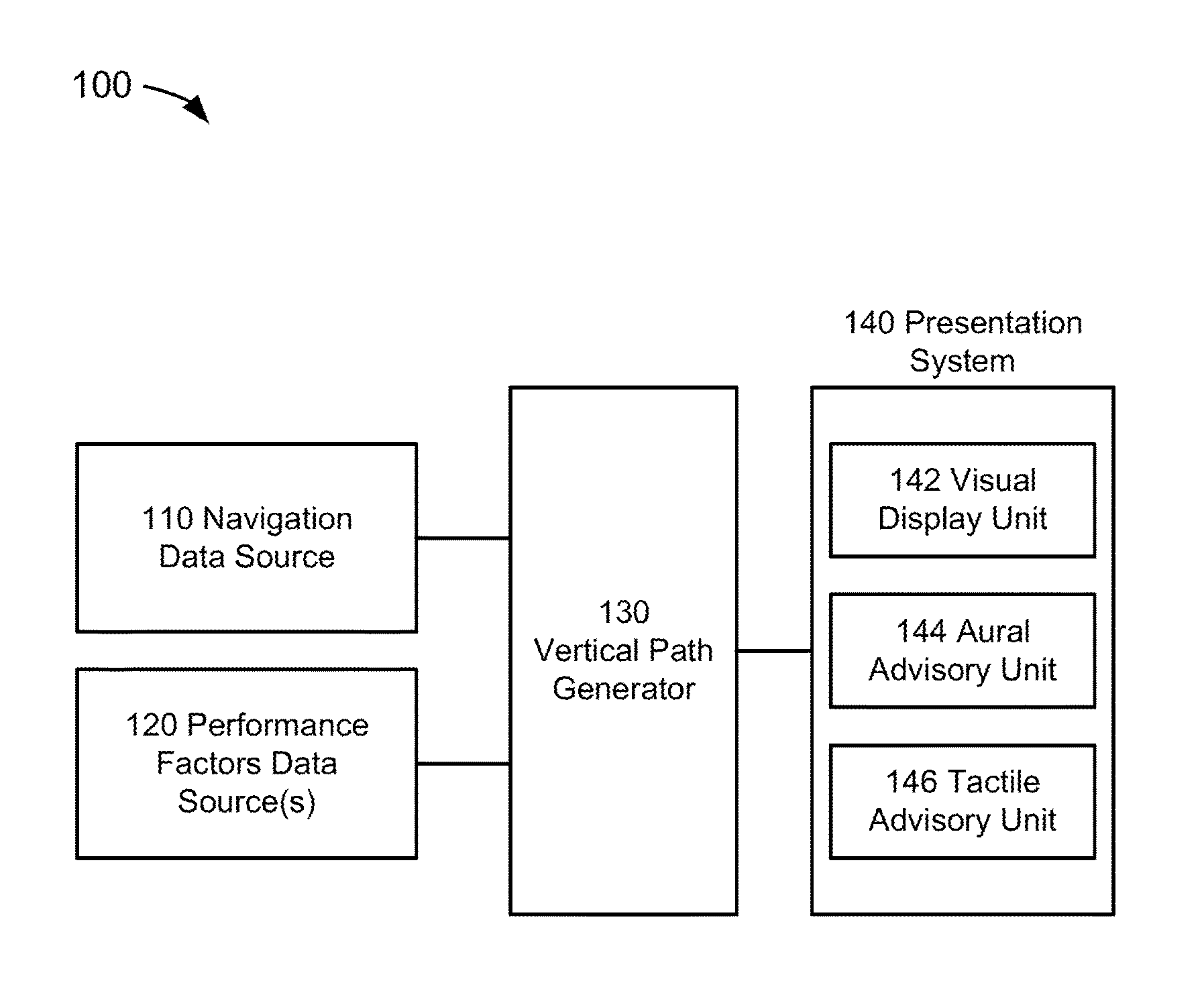
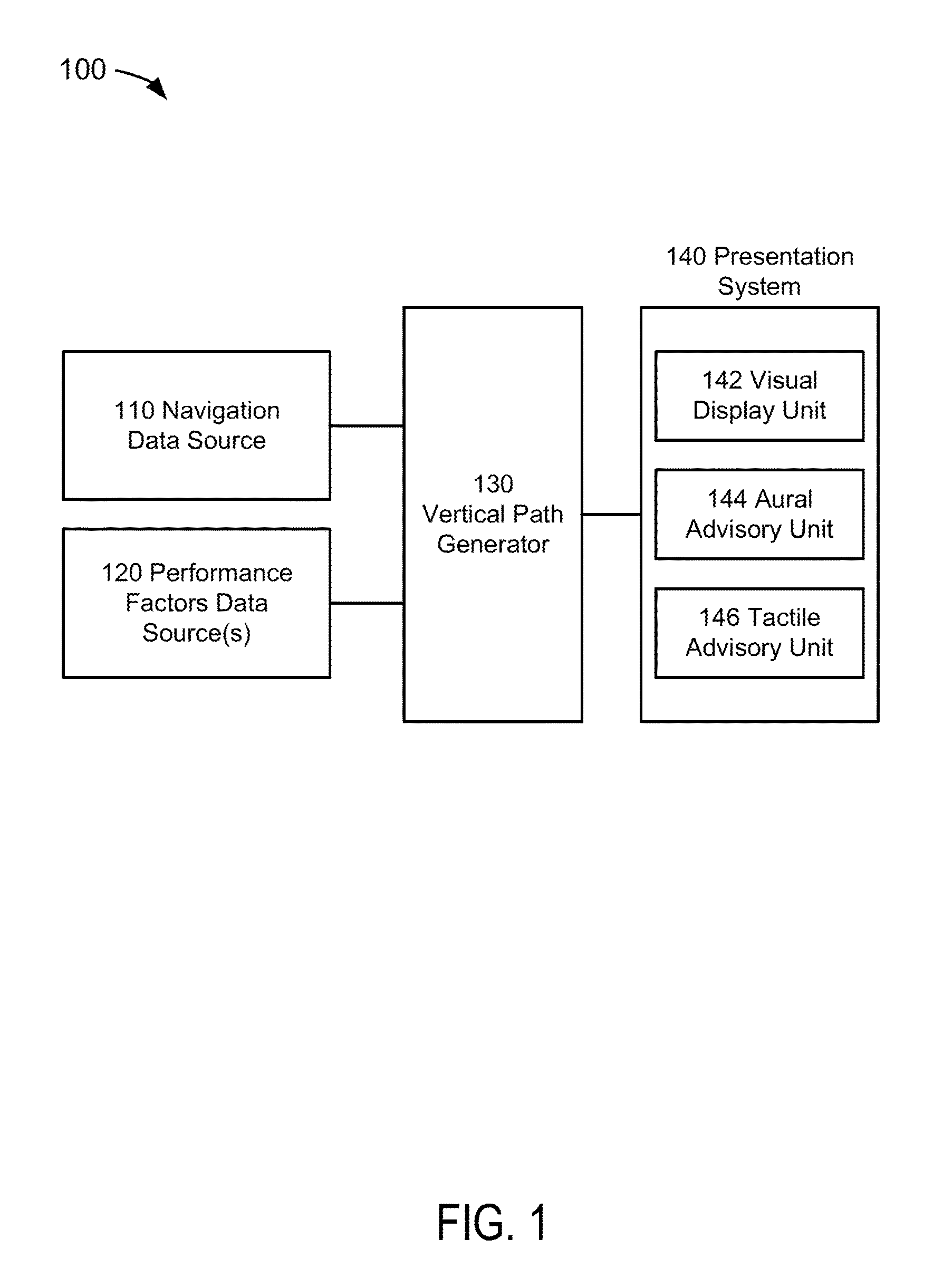
[0022]FIG. 1 depicts a functional block diagram of an embodiment of a vertical path profile generating system 100 suitable for implementation of the techniques described herein. The functional blocks of the system 100 include a navigation data source 110, a performance factors data source 120, a vertical path generator (“VPG”) 130, and a presentation system 140.

[0023]The navigation data source 110 could include any source(s) which provides navigation data information in an aircraft. The navigation d...


PUM


Abstract

Present novel and non-trivial system, device, and method for generating a vertical path profile are disclosed. The vertical path profile generating system is comprised of a source of navigation data, a source of performance factors data, a vertical path generator (“VPG”) and a presentation system. The VPG may be configured to receive the navigation data representative of takeoff runway information; receive the performance data may be representative of aircraft performance factors; determine a first vertical path and / or second vertical path as a function of criteria employing the navigation data and the performance data; generate presentation data responsive to the determination; and provide the presentation data to one or more presentation devices comprised of, in part, a visual display unit configured to display a first takeoff path profile and / or a second takeoff path profile.

Description

BACKGROUND OF THE INVENTION[0001]Field of the Invention[0002]This invention pertains generally to the field of aircraft display units that present information to the pilot of an aircraft.[0003]Description of the Related Art[0004]Aviation governing authorities such as the Federal Aviation Administration (“FAA”) of the Unites States have developed constraints on aircraft climb performance. In the United States, the FAA has published these constraints in Part 25 of the Federal Aviation Regulations. Constraints on aircraft climb performance include minimum climb gradients with one or more engines inoperative during a plurality of take-off (“T / O”) segments along with defined aircraft configurations corresponding to the T / O: a ground roll segment, a first segment defining first climb performance criteria, a second segment defining second climb performance criteria, a third segment defining acceleration criteria, and a fourth segment defining third climb performance criteria.[0005]The FAA ...

Claims


Application Information

Patent Timeline
IPC IPC(8): G01C23/00G08G5/00B64D45/00
CPCG08G5/0065B64D45/00G01C23/00G05D1/0661G08G5/0021
Inventor KOLEK, KIRK A.ARONS, NORM W.VOLNER, MARK W.
Owner ROCKWELL COLLINS INC
Learn More