Display panel for display device and method for detecting defects of signal lines for display devices
a display device and display panel technology, applied in static indicating devices, instruments, non-linear optics, etc., can solve the problems of difficult detection of whether, precise location of shorted and/or opened signal lines, and inability to determine whether, so as to increase the resistance between adjacent signal lines and eliminate signal interference
- Summary
- Abstract
- Description
- Claims
- Application Information
AI Technical Summary
Benefits of technology
Problems solved by technology
Method used
Image
Examples
first embodiment
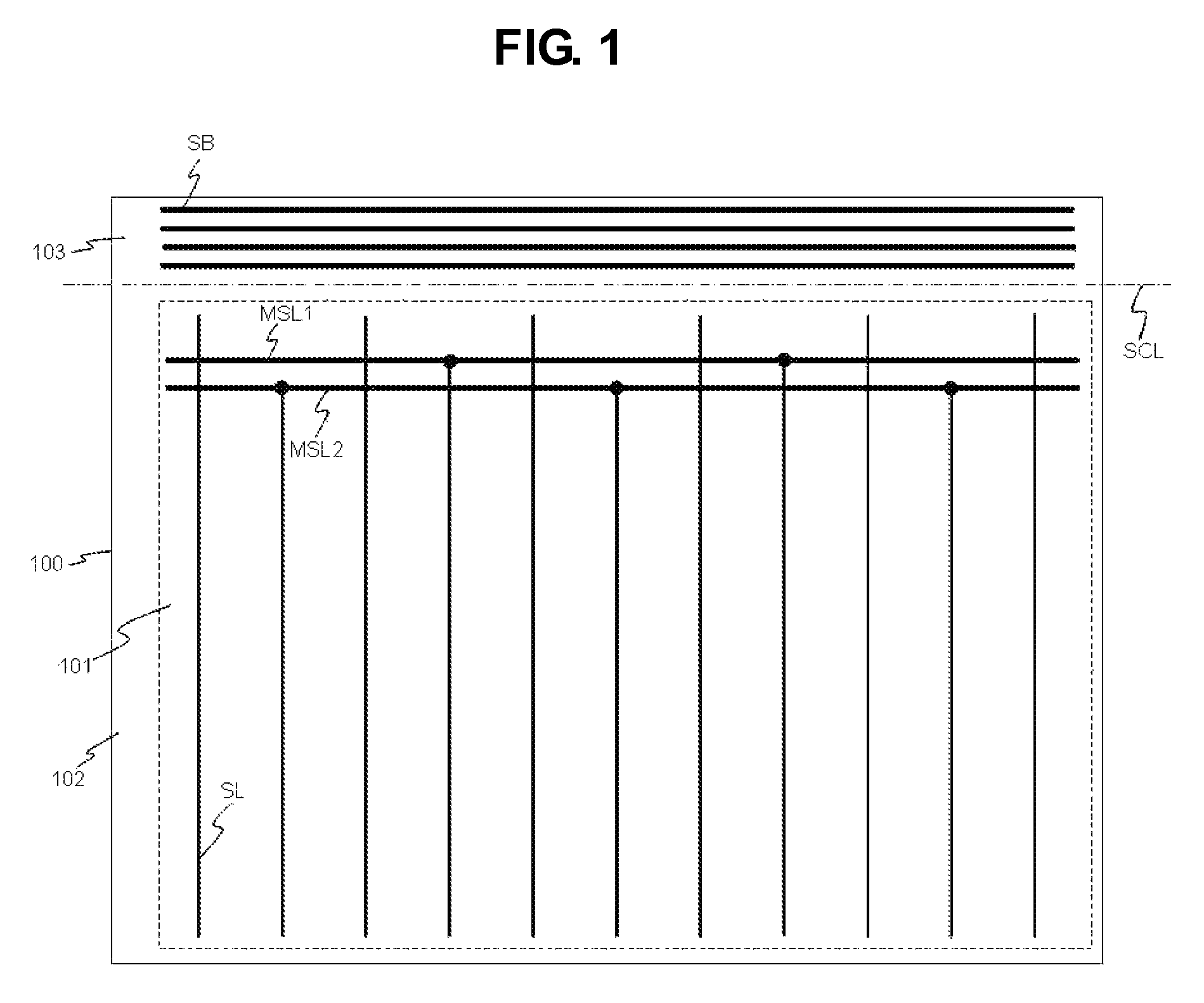
[0046]FIG. 1 illustrates a display panel for display devices in accordance with the present invention.
[0047]The display panel for display devices in accordance with the first embodiment of the present invention, as shown in FIG. 1, includes a substrate 100 on which a plurality of signal lines SL to transmit various signals required by pixels is formed.
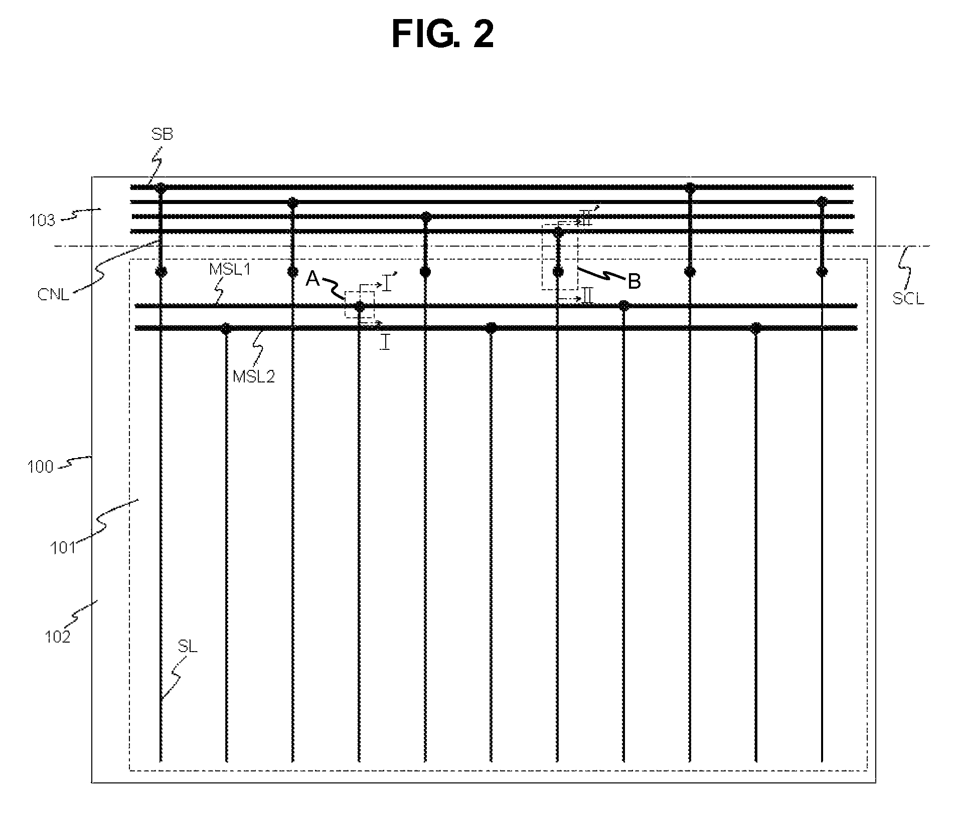
[0048]The substrate 100 is divided into a display area 101, a non-display area 102 and a shorting bar area 103. The substrate 100 shown in FIG. 1 is a lower substrate from among two substrates of the display panel, and FIG. 1 does not illustrate an upper substrate. The shorting bar area 103 is removed from the substrate 100 after a final test. For example, the shorting bar area 103 is removed from the substrate 100 by cutting the substrate 100 along a scribing line SCL of FIG. 1.
[0049]The pixels and the signal lines SL are formed in the display area 101, as described above. Further, first and second main signal transmission lines MSL1 ...
second embodiment
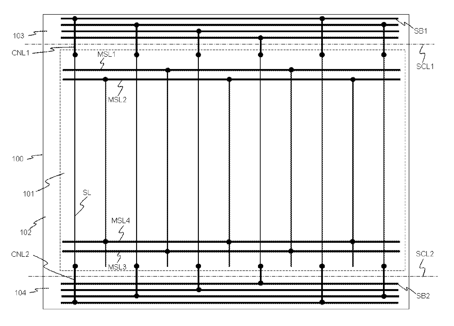
[0094]FIG. 8 illustrates a display panel for display devices in accordance with the present invention.
[0095]The display panel for display devices in accordance with the second embodiment of the present invention, as shown in FIG. 8, includes a substrate 100 on which a plurality of signal lines SL to transmit various signals required by pixels is formed.
[0096]The substrate 100 is divided into a display area 101, a non-display area 102, a first shorting bar area 103 and a second shorting bar area 104. The substrate 100 shown in FIG. 8 is a lower substrate from among two substrates of the display panel, and FIG. 8 does not illustrate an upper substrate.
[0097]The pixels and the signal lines SL are formed in the display area 101, as described above. Further, first to fourth main signal transmission lines MSL1 to MSL4 are formed in the display area 101. Alternatively, the first to fourth main signal transmission lines MSL1 to MSL4 may be formed in the non-display area 102 rather than the ...
PUM
| Property | Measurement | Unit |
|---|---|---|
| drive voltages | aaaaa | aaaaa |
| voltage | aaaaa | aaaaa |
| transmission | aaaaa | aaaaa |
Abstract
Description
Claims
Application Information
 - R&D
- Intellectual Property
- Life Sciences
- Materials
- Tech Scout
- Unparalleled Data Quality
- Higher Quality Content
- 60% Fewer Hallucinations
Browse by: Latest US Patents, China's latest patents, Technical Efficacy Thesaurus, Application Domain, Technology Topic, Popular Technical Reports.
© 2025 PatSnap. All rights reserved.Legal|Privacy policy|Modern Slavery Act Transparency Statement|Sitemap|About US| Contact US: help@patsnap.com


