Remote control and display system

A remote control and control signal technology, applied in signal transmission systems, electrical signal transmission systems, instruments, etc., can solve the problems of calculating physiological information, inapplicability, etc.

Active Publication Date: 2013-06-05
PIXART IMAGING INC
View PDF5 Cites 6 Cited by
  • Summary
  • Abstract
  • Description
  • Claims
  • Application Information

AI Technical Summary

Problems solved by technology

[0007] However, because the blood oxygen saturation meter detects the light intensity change of the penetrating light, it will detect different light intensity signals with different parts to be tested; in addition, when the part to be te

Method used


Image

  • Remote control and display system
  • Remote control and display system
  • Remote control and display system

Examples


Embodiment Construction

[0043] In order to make the above and other objects, features and advantages of the present invention more apparent, a detailed description will be given below with reference to the accompanying drawings. In the description of the present invention, the same components are denoted by the same symbols, and will be described first.

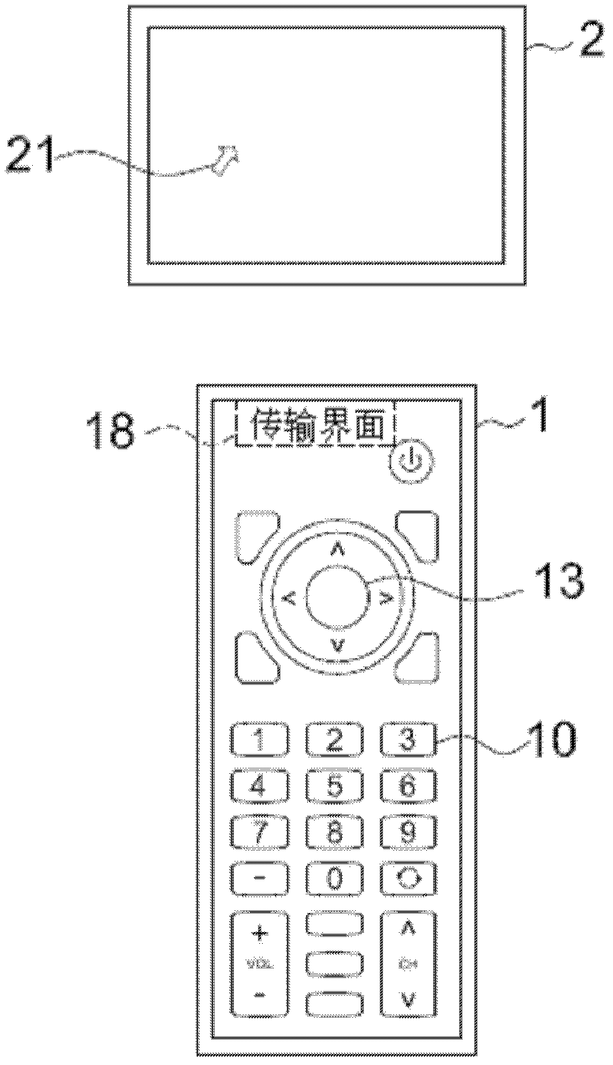
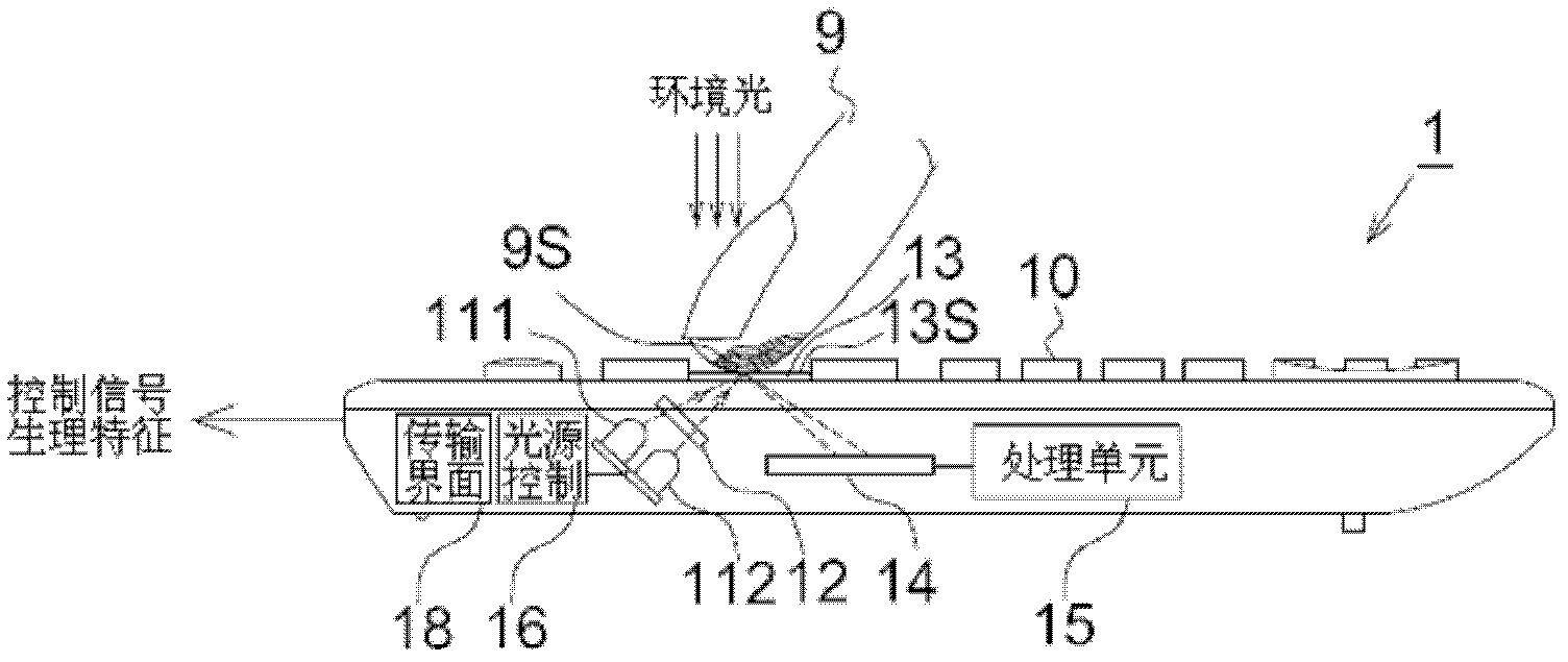
[0044] Figure 2Ais a schematic diagram of an image system according to an embodiment of the present invention, including a remote controller 1 and a display device 2 . The display device 2 can be, for example, a TV, a projection screen, a game machine screen, a computer screen or other display devices for displaying images. With respect to the display device 2, the remote controller 1 can be a TV remote controller, a projection screen remote controller, a game console remote controller, a computer remote controller and other remote controllers, and is used to control the display device 2 to update display content or images and Displaying physiolo...


PUM


Abstract

A remote control comprises a plurality of control buttons, an optical ginger mouse and a transmission interface. The control buttons are used for triggering control signals. The optical ginger mouse is used for detecting physiological features and displacement. The transmission interface is used for outputting the control signals, the physiological feature and the displacement to a display device. The invention further provides a display system.

Description

technical field [0001] The invention relates to a man-machine interface system, in particular to a remote controller and a display system with a user's physiological feature detection function. Background technique [0002] An optical finger mouse (OFM) is generally suitable for matching with other electronic devices due to its small size. The known optical finger mouse is used to detect the light intensity change of the reflected light on the surface of the user's finger, so as to judge the contact state of the finger and the displacement of the finger relative to the touch surface. However, with the development of industrialization, users spend more and more time using various electronic devices, even exceeding physical load without realizing it. Therefore, if the electronic device has the function of detecting the physiological characteristics of the user and can display the physiological condition at that time, the situation of overuse can be avoided. [0003] It is kn...

Claims


Application Information

Patent Timeline
IPC IPC(8): G08C17/02G08C19/00
Inventor 古人豪高铭璨黃森煌
Owner PIXART IMAGING INC
Why Eureka
Try Eureka