Multi level cable bus system with modular cable trays

a cable bus system and cable bus technology, applied in the direction of bus-bar/wiring layout, electrical apparatus, substations, etc., can solve the problems of b>12/b> being both cumbersome and time-consuming, and the use of split chocks, so as to minimize the possibility of excessive heating of cable conductors and minimize phase impedance

Active Publication Date: 2017-02-28
PAWLUK MARLYN
View PDF7 Cites 3 Cited by
  • Summary
  • Abstract
  • Description
  • Claims
  • Application Information

AI Technical Summary

Benefits of technology

[0014]The present invention provides a cable bus system for the mounting and positioning of electrical power cables used to conduct high amperature, polyphase electrical current up to 8,000 Amps. The cable bus system is configured to ensure that electrical impedance along each parallel conductor cable is identical to provide equal current load sharing, while minimizing phase impedance and the generation of cable mutual heating thereby. In the cable bus system, a predetermined number of electrical cables are fixed in position relative to each other to minimize the possibility of excessive heating of cable conductor insulation as a result of the heat generated by the transmission of electricity therealong.

Problems solved by technology

As the amperature electric current to be delivered increases to higher values, the three conductor constructions become less economical and feasible to use due to the damaging mutual heating of the conductor insulation.
In particular, the use of split chocks 26a,26b,26c to support and position electrical cables 12 are both cumbersome and time consuming.
In certain cases physical space constraints may prevent the installation of bolts necessary to lock the blocks together.
Because of the longitudinal length spacing between the sets of split blocks and the varying surface contour of each split block 24, this in turn necessitates the use of labour intensive cable rollers to avoid cable damage, increasing both the time and cost of installation.
The correction of hole sizes is both difficult and costly, if deemed possible, and therefore requires the manufacturing and replacement of the split blocks.
Another disadvantage is that the cables used are normally heavier, larger sized conductors with relatively thin insulation which can be readily ruptured and fail at the three foot interval support locations, as a result of commonly occurring and damaging electrical system fault forces.
If ventilation openings in the top panel 18 are inadvertently covered by debris or the like, this disadvantageously may result in localized cable hot spots along the raceway 22 as a result of blockage of required airflow.
More problematic however, if cables 12 at a lower level require removal or replacement as a result of damage or failure, with prior art systems it is necessary to first completely remove and thereafter reinstall all overlying chock blocks 26c,26d and the upper cable layers from the raceway 22 at significantly increased time, cost and difficulty.
Another disadvantage of the prior art of cable bus systems are typically installed above ground level in order to ensure that free flowing air passing through the vented covers dissipates undesirable heat generated by cables away from the enclosure.
Heat trapped within the vicinity of the high amperage cables will cause the ambient temperature to rise, causing premature failure of the cable installation or necessitating the substantial derating of the allowable cable amperature, which can become cost prohibitive.
Due to the slow rates of heat transfer away from the heat generating cables due to a lack of airflow, the amperage of cables installed in such mediums are restricted both technically and by industry standards to approximately one half of that allowable for cables which are continuously cooled by air movement.
When a power cable circuit is conventionally installed partially underground with the balance of the circuit installed where there is open airflow, the allowable amperage for the cables in the total circuit length is restricted to the lower underground amperage values resulting in uneconomical installation practices.

Method used


Image

  • Multi level cable bus system with modular cable trays
  • Multi level cable bus system with modular cable trays
  • Multi level cable bus system with modular cable trays

Examples


Embodiment Construction

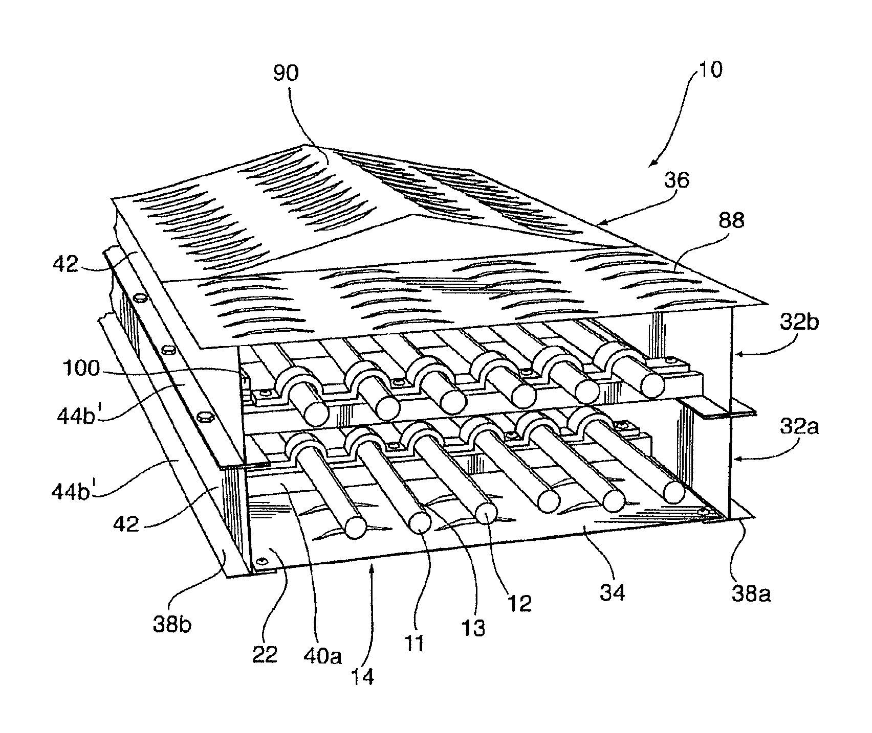
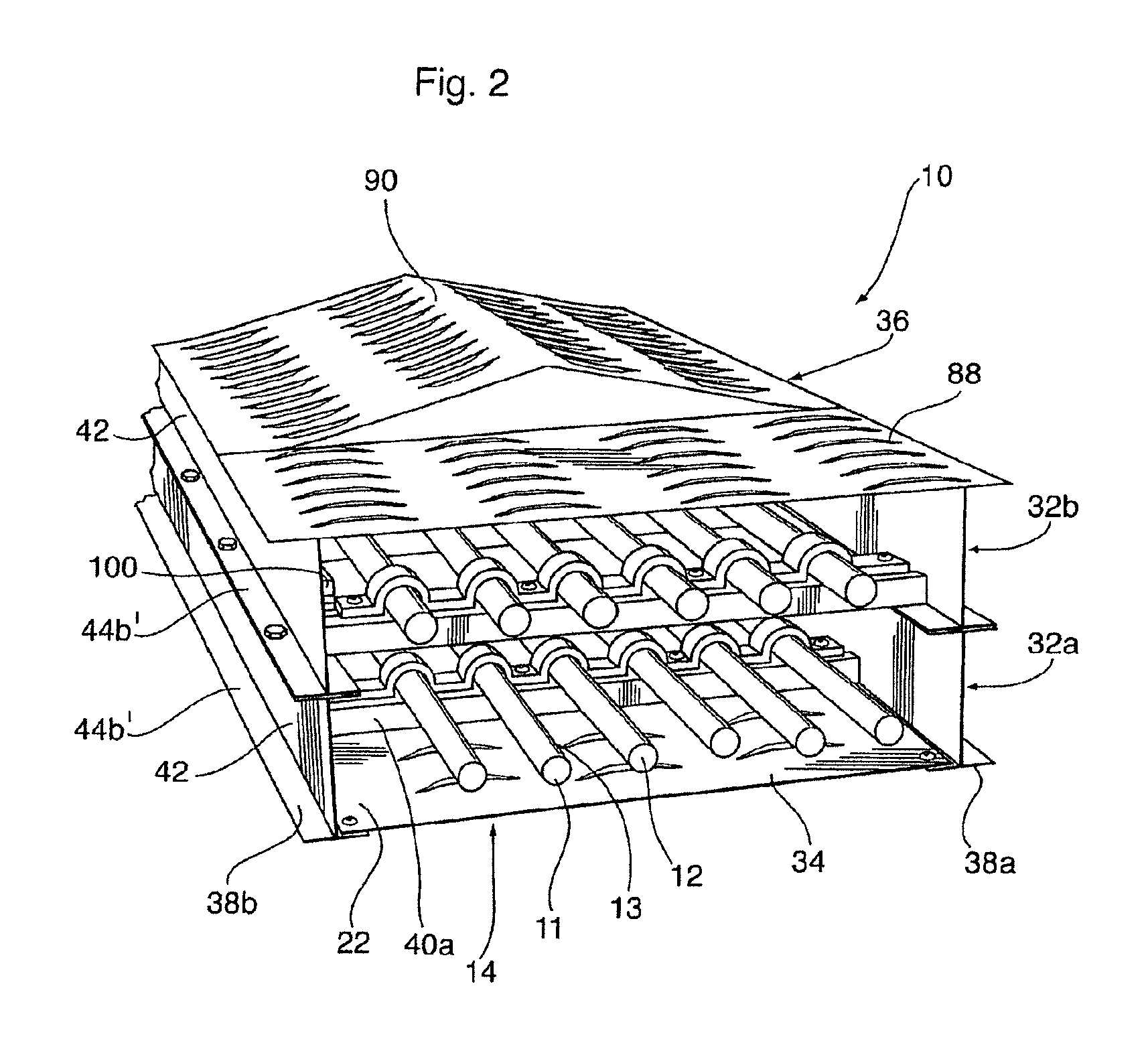
[0055]Reference is made to FIGS. 2 and 3 which illustrate a cable bus system 10 in accordance with a preferred embodiment of the invention used in the distribution and transmission of three-phase electrical power. As will be described, the cable bus system 10 is formed having one and preferably a number of aluminum (or other metal) enclosures 14 which define a longitudinally extending raceway 22 used to house and protect a series of insulated electrical cables 12.

[0056]FIG. 2 shows best each of the electrical cables 12 as comprising high amperature, low, medium and high voltage electrical cables which are provided in an electrically conductive core 11 layer which is typically formed of stranded copper wire, and an electrically insulating outer coating or sheath 13. In the embodiment shown, the cables 12 are longitudinally aligned in two vertically stacked, lower and upper cable arrays 30a,30b, each consisting of six cables 12 in parallel. As shown schematically in FIG. 3, the curren...


PUM


Abstract

A cable bus system for the mounting and positioning of high amperature, from low to high voltage electrical power cables transmitting polyphase electrical current. The cable bus system included a ventilated enclosure used to protect electrical cables mounted therein. The enclosure is provided with multiple modular cable trays which are bolted together in a stacked arrangement to form a single multi-level cable raceway. The enclosure is further provided with ventilated top and bottom covers which are secured respectively to the top and bottom of the uppermost and bottom most cable trays to define the enclosed metal circuit. The cable bus system is capable of transmitting the same highest allowable “free air” cable amperature in both above and underground installations, effectively improving the transmission of electrical power from one end to the other end, in installations where a transition of electrical power from below ground to above ground is either necessary or economically preferable. For the underground portion, the cable bus is installed in the encasement that is uniquely offset vented or power cooled to meet the cable high amperage requirements. The cable bus system is also suitable for high vertical rise installations when utilizing anti cable slip mechanism or technique.

Description

RELATED APPLICATIONS[0001]This application is a continuation of U.S. patent application Ser. No. 14 / 026,758, filed Sep. 13, 2013, and which is a continuation-in-part of U.S. patent application Ser. No. 12 / 929,671, filed 8 Feb. 2011, now U.S. Pat. No. 8,558,112 B2.SCOPE OF THE INVENTION[0002]The present invention relates to a cable bus system for use in the distribution of electric power, and more particularly an expandable cable bus system for the distribution and / or transmission of low, medium and high voltage, high amperage, polyphase alternating-current having amperatures ranging up to 8,000 Amps, and / or at voltages of up to 230,000 volts.BACKGROUND OF THE INVENTION[0003]In power generation and transmission, electrical generator coils or windings are used to produce alternating electric current. To effect the more economical transmission of produced electric current, polyphase transmission systems have been developed. Conventionally, most polyphase power transmission is effected ...

Claims


Application Information

Patent Timeline
Patent Type & Authority Patents(United States)
IPC IPC(8): H02G3/04H02B1/20H02G3/03H02B7/08H02G9/08H02G9/04
CPCH02G3/03H02B1/20H02B7/08H02G3/0437H02G9/08H02G9/04
Inventor PAWLUK, ROBERT R.
Owner PAWLUK MARLYN
Why Eureka
Try Eureka