
Performance monitoring and correction in a touch-sensitive apparatus

a technology of performance monitoring and performance correction, applied in the direction of instruments, computing, electric digital data processing, etc., can solve the problems of particularly sensitive approaches to validity changes among data samples, artifacts in signal interaction patterns that are mistaken for touches, etc., to reduce the need to activate error correction and stabilize processing

Active Publication Date: 2017-03-07
FLATFROG LAB
View PDF51 Cites 34 Cited by
  • Summary
  • Abstract
  • Description
  • Claims
  • Application Information

AI Technical Summary

Benefits of technology

The patent text describes a technique for improving the detection of signals in touch systems that operate by propagating signals across a touch surface. The technique involves using an error correction step to maintain the relative signal transmission between different repetitions of the signals. This helps to reduce the need for activating the error correction and promotes a stabilization of the processing. The technique also allows for the identification of unreliable signal values and their replacement with valid values, which further improves the accuracy of the touch system.

Problems solved by technology

As will be further explained below in relation to detailed examples, simply removing or adding a data sample based on the validity change is likely to cause local errors in the interpolated sinogram, which in turn may cause artifacts in the signal interaction pattern that are mistaken for touches.
Such an approach has been found to be particularly sensitive to validity changes among the data samples.

Method used


Image

  • Performance monitoring and correction in a touch-sensitive apparatus
  • Performance monitoring and correction in a touch-sensitive apparatus
  • Performance monitoring and correction in a touch-sensitive apparatus

Examples


first embodiment

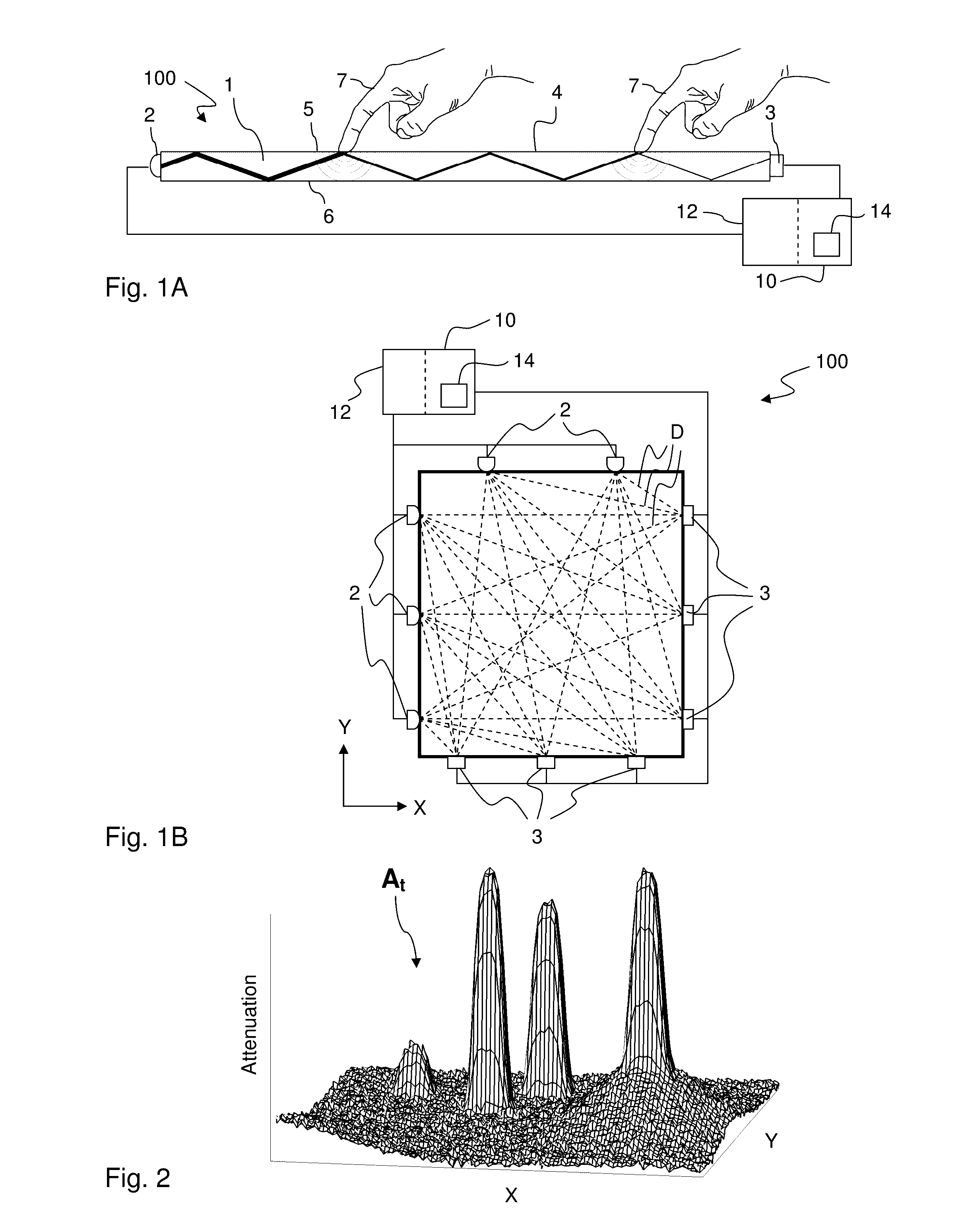
[0063]In a first embodiment, further discussed in WO2010 / 064983 and WO2011 / 049512, as well as WO2012 / 121652, the reference values are given by the output signal at a certain calibration time point when no touching object (finger, stylus, etc) is present on the touch surface, such as when the assembly of the apparatus 100 is finalized, at start-up, or when a user initiates a reset operation of the apparatus 100. These reference values, also denoted calibration values and represented by I0, may be stored in a memory unit of the device 10. By using I0, the reconstructed attenuation pattern At will represent the total accumulated attenuation on the touch surface since the calibration time point. Such an attenuation pattern At is illustrated in FIG. 2 as a 3D plot in the coordinate system X,Y of the touch surface (cf. FIG. 1B).

[0064]In a second embodiment, the reference values are updated repeatedly during operation of the apparatus, e.g. at time intervals Δt, by setting the reference va...

second embodiment

[0069]In a second implementation of the second embodiment, disclosed in further detail in PCT / SE2012 / 051006, filed on Sep. 24, 2012, the total attenuation pattern At is generated by accumulating the difference pattern across the time intervals Δt: At=At-Δt+dAt. In a variant of the second implementation, a total pattern, which is compensated for the influence of contaminations on the touch surface and denoted an offset pattern ot, is generated by accumulating the difference pattern across the time intervals Δt: ot=o′t-Δt+dAt. Before being used for accumulation in the next time interval, each pixel in the offset pattern ot is compensated for contamination, e.g. according to an exponential forget algorithm:

[0070]ot′=(1-ɛ)·ot⁢{ɛ=0,if⁢⁢touch⁢⁢in⁢⁢pixel⁢⁢of⁢⁢otɛ=0.1,if⁢⁢no⁢⁢touch⁢⁢in⁢⁢pixel⁢⁢of⁢⁢ot

[0071]which will cause the offset pattern ot to gradually approach zero attenuation in regions without touch interaction, while other pixels / regions will have a value representative of the local...


PUM


Abstract

Touch sensitivity is enabled using a touch system that comprises a panel configured to conduct signals, e.g. by TIR, along detection lines across a touch surface. A signal processor operates in a sequence of repetitions to: generate data samples that represent detected signal energy on the actual detection lines; generate based on the data samples, an interpolated sinogram comprising interpolation samples that represent fictitious detection lines which have a desired location on the touch surface; and reconstruct a signal interaction pattern for the touch surface based on the interpolated sinogram. The signal processor implements an error correction to counteract the influence of a change in validity status for a data sample among the data samples, by identifying interpolation samples affected by the change in validity status, and by setting each identified interpolation sample to a value that maintains a relative signal transmission of the fictitious detection line from a former repetition.

Description

CROSS-REFERENCE TO RELATED APPLICATIONS[0001]The present application is related to the following applications, which are all incorporated herein in their entirety by this reference: WO2010 / 064983, WO2011 / 049512, WO2011 / 078769, WO2011 / 139213, WO2012 / 121652, WO2012 / 158105, PCT / SE2012 / 051006 filed on Sep. 24, 2012, and PCT / SE2012 / 51073 filed on Oct. 8, 2012.[0002]The present application claims the benefit of PCT / SE2013 / 050064 filed Jan. 29, 2013, Swedish patent application No. 1250064-1, filed 31 Jan. 2012, and U.S. provisional application No. 61 / 592,641, filed 31 Jan. 2012, all of which are incorporated herein by reference in their entirety.TECHNICAL FIELD[0003]The present invention relates to touch sensing systems and data processing techniques in relation to such systems, and in particular to techniques for performance monitoring and correction.BACKGROUND ART[0004]Touch sensing systems (“touch systems”) are in widespread use in a variety of applications. Typically, the touch sensing...

Claims


Application Information

Patent Timeline
Patent Type & Authority Patents(United States)
IPC IPC(8): G06F3/041G06F3/042
CPCG06F3/0418G06F3/042G06F3/0428G06F2203/04109G06F3/04186G06F3/0421G06F3/047
Inventor CHRISTIANSSON, TOMASBJORKLUND, ANDREASWALLANDER, MATS PETTEROHLSSON, NICKLAS
Owner FLATFROG LAB
Learn More