
Multi-input multi-output antenna system

a multi-input, multi-output technology, applied in the field of wireless communication, can solve the problems of limited application, limited radiation performance, and limited application of mimo technology in cellular mobile communication systems, and achieve high isolation and good radiation performan

Active Publication Date: 2017-03-07
ZTE CORP
View PDF22 Cites 1 Cited by
  • Summary
  • Abstract
  • Description
  • Claims
  • Application Information

AI Technical Summary

Benefits of technology

[0015]Compared with the prior art, the present invention has the following advantages:
[0018]3. The parasitic element is introduced as a decoupling unit such that not only the problem of coupling between the antenna elements is solved effectively, but also the radiation unit far away from the parasitic element has a wide bandwidth in the required frequency band, while the coupling at other frequencies other than the central frequency in this frequency band is relatively small as well.

Problems solved by technology

With the rapid development of the wireless communication technology, the serious shortage of frequency resources has increasingly become a bottleneck which restrains the development of the wireless communication industry.
Contradictions in many aspects have been manifested in design and system scheme stages of LTE terminal antennas.
However, up to now, the MIMO technology has seldom implemented commercially in cellular mobile communication systems and is limited by some factors in applications in 3G.
One of important factors is the antenna problem.
However, due to limitations of size and structure of the receiver or transmitter, antenna elements usually are arranged in a limited space as many as possible such that miniaturization of the antennas and coupling between the multiple antennas have become one of problems required to be solved urgently.
Increasing of the antenna spacing is often limited by the installation volume of antennas in practical applications; both introducing the EBG structure and indenting in the floor require a larger floor, which goes against miniaturization of the antennas as well.

Method used


Image

  • Multi-input multi-output antenna system
  • Multi-input multi-output antenna system
  • Multi-input multi-output antenna system

Examples


Embodiment Construction

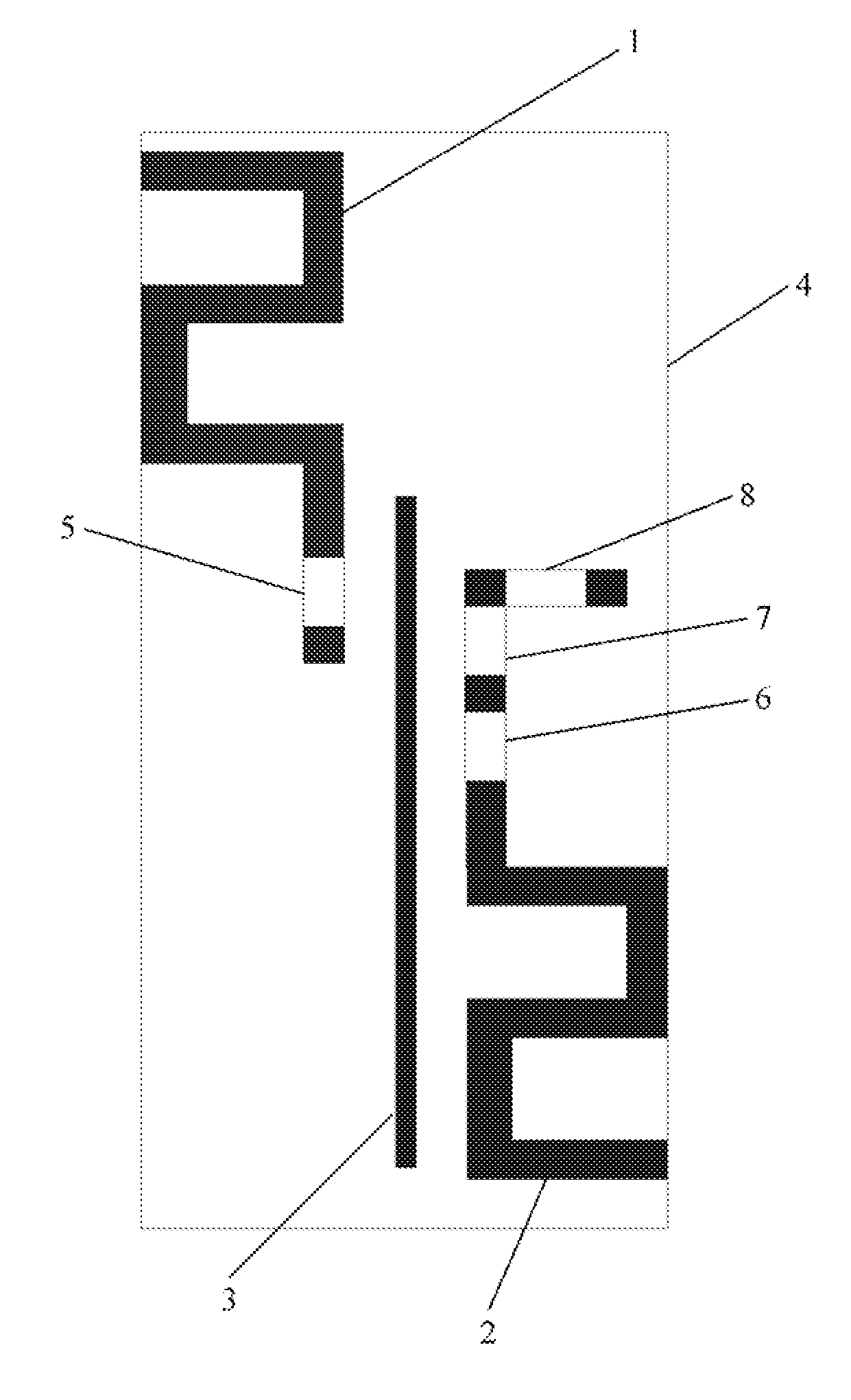
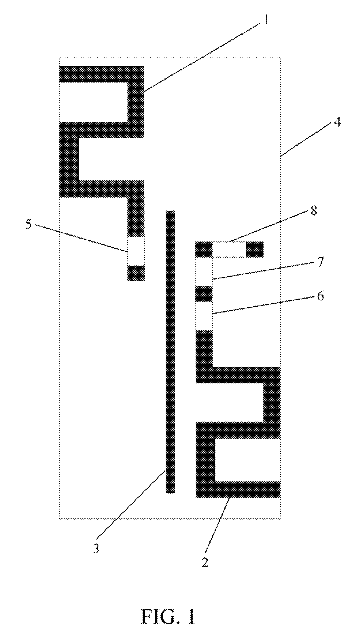
[0031]In a multi-antenna system, radiation is generated when a single antenna is excited. Since the spacing between antenna elements is small, scattering is caused due to interaction between adjacent antenna elements, and thus the isolation between antennas is low. Instead of using the traditional method for increasing the isolation in the multi-antenna system, the present invention decreases coupling between the adjacent antennas by placing a parasitic element between adjacent antennas as a reflection unit.

[0032]The monopole antenna structure is widely used in a variety of communications antenna designs. The present invention uses monopole antennas with the zigzag structure to implement miniaturization of the MIMO antennas. Load impedance of the antennas affects standing waves at the antenna ports, therefore after a decoupling unit is added in the multi-antenna system, impedance matching of the antennas is required to be performed. The present invention uses the lumped elements to ...


PUM


Abstract

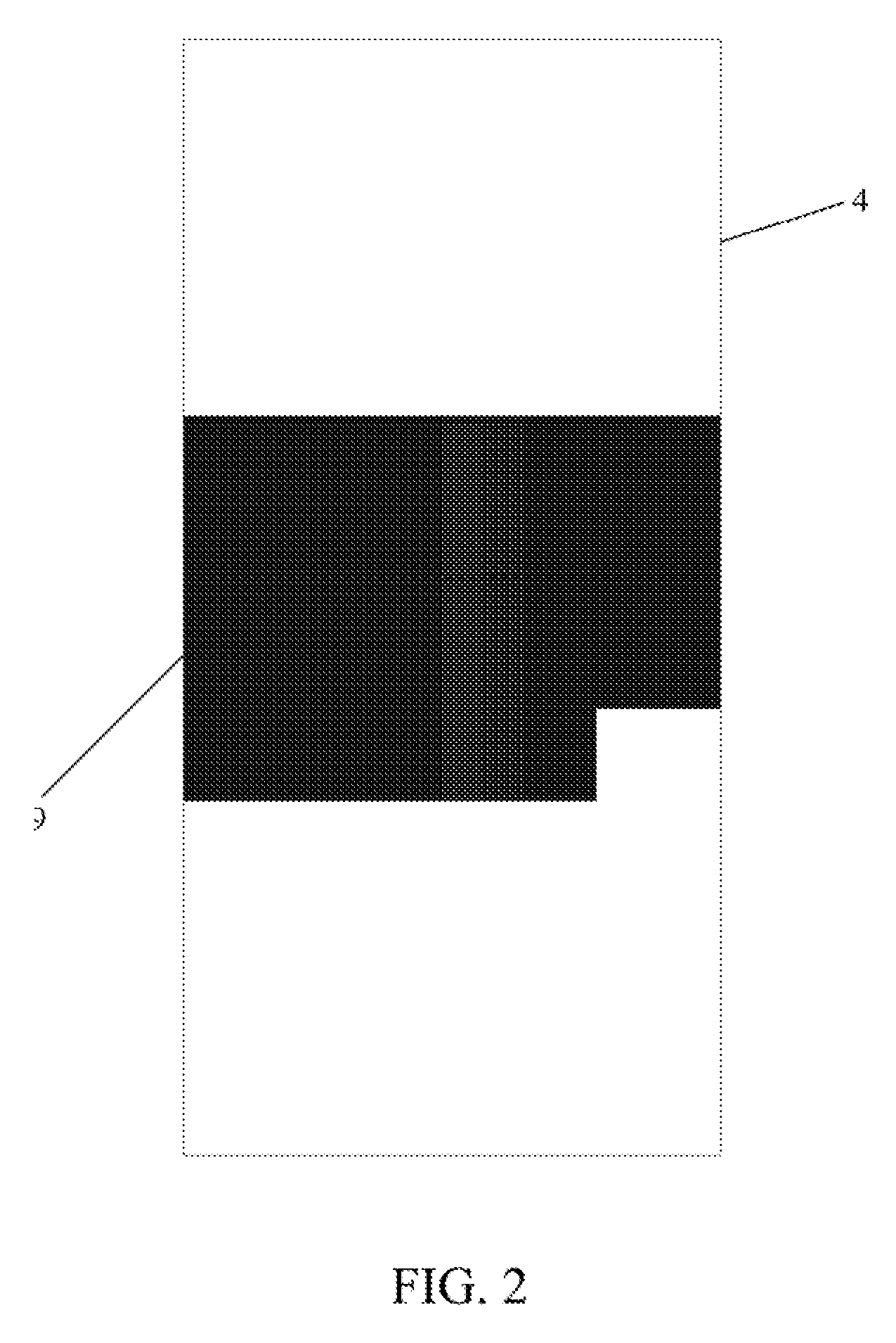
The present invention discloses a multi-input multi-output antenna system comprising a first radiation unit, a second radiation unit, a radiation floor, a dielectric plate and a parasitic element. The first radiation unit, the second radiation unit and the parasitic element are printed on an upper surface of the dielectric plate, and the radiation floor is printed on a lower surface of the dielectric plate. The first radiation unit and the second radiation unit are planar monopole antennas, and the parasitic element is positioned between the first radiation unit and the second radiation unit. The system in accordance with the present invention can implement miniaturization of the antennas, and ensure two ports of an antenna have high isolation while maintaining good radiation performance.

Description

TECHNICAL FIELD[0001]The present invention relates to the field of wireless communications, and more particularly, to a MIMO (Multiple Input Multiple Output) antenna system.BACKGROUND OF THE RELATED ART[0002]With the rapid development of the wireless communication technology, the serious shortage of frequency resources has increasingly become a bottleneck which restrains the development of the wireless communication industry. The wireless communication is developing towards the direction of large capacity, high transfer rate and high reliability such that how to maximize the spectrum utilization rate for limited spectrum resources has become a hot subject in current research. With the development of the LTE (Long Term Evolution) industry, currently MIMO antenna systems necessary for 4G have brought new challenges to terminal antenna design and evaluation: on the one hand, users require user experience of miniaturization and high quality, on the other hand, the MIMO antenna systems r...

Claims


Application Information

Patent Timeline
Patent Type & Authority Patents(United States)
IPC IPC(8): H01Q1/52H01Q1/38H01Q9/42H01Q1/50H01Q21/28H01Q1/24
CPCH01Q1/523H01Q1/243H01Q1/38H01Q1/50H01Q1/521H01Q9/42H01Q21/28
Inventor AI, HAOJIANG, HUIZHANG, LU
Owner ZTE CORP
Learn More