Array of two twin-reflector antennas mounted on a common support and a satellite comprising this array

a technology of twin-reflector antennas and satellites, which is applied in the direction of antenna details, antennas, antenna adaptation in movable bodies, etc., can solve the problems of increasing the cost, reducing the radio-frequency performance of the antenna, and no solution currently exists for arranging two twin-reflector antennas. achieve the effect of increasing the optical length of the two antennas and improving the performance level

Active Publication Date: 2017-03-07
THALES SA
View PDF8 Cites 0 Cited by
  • Summary
  • Abstract
  • Description
  • Claims
  • Application Information

AI Technical Summary

Benefits of technology

[0007]The object of the invention is to overcome the disadvantages of known twin-reflector antennas and implement an array of two twin-reflector antennas which can be disposed on the same side of a satellite and which enable the focal length of the two antennas to be increased, and to guarantee a performance level higher than that obtained with known twin-reflector antenna arrays.

Problems solved by technology

However, this type of antenna comprises reduced radio-frequency performance.
This poses problems of arrangement, since the Earth side of the satellite is generally intended for the installation of antennas and equipment linked to the overall purpose of the satellite.
Furthermore, these antennas are complex and require the installation of a deployment system for the secondary reflectors, which increases the cost.
To the best of our knowledge, no solution currently exists for arranging two twin-reflector antennas, at least one of the two antennas having an F / D ratio greater than 1.1, on the same side of a satellite due to the size of the secondary reflectors.
The problem is that this limits the number of antennas that can be installed on a satellite and therefore limits the number of tasks that can be performed.

Method used


Image

  • Array of two twin-reflector antennas mounted on a common support and a  satellite comprising this array
  • Array of two twin-reflector antennas mounted on a common support and a  satellite comprising this array
  • Array of two twin-reflector antennas mounted on a common support and a  satellite comprising this array

Examples


Embodiment Construction

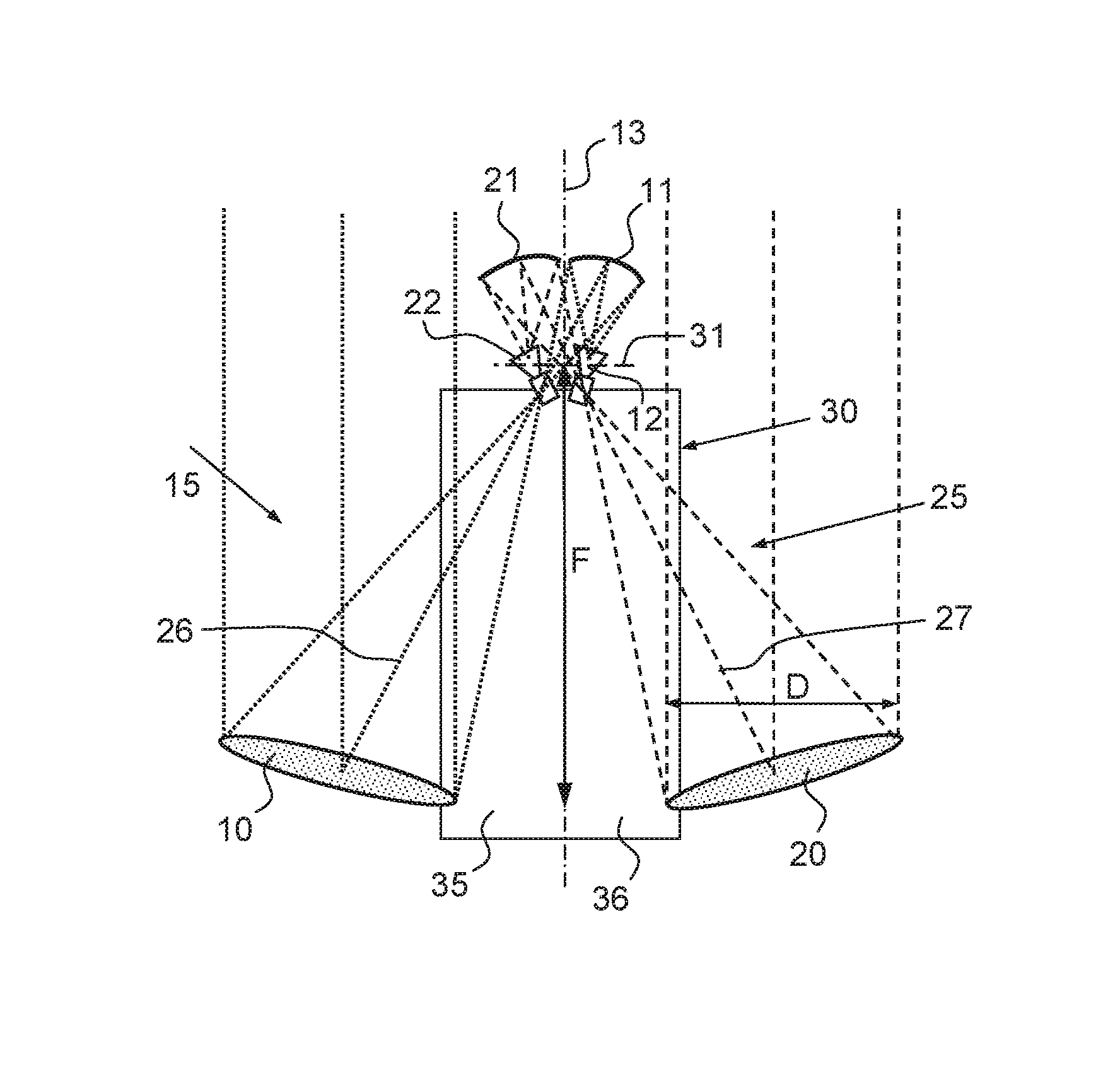
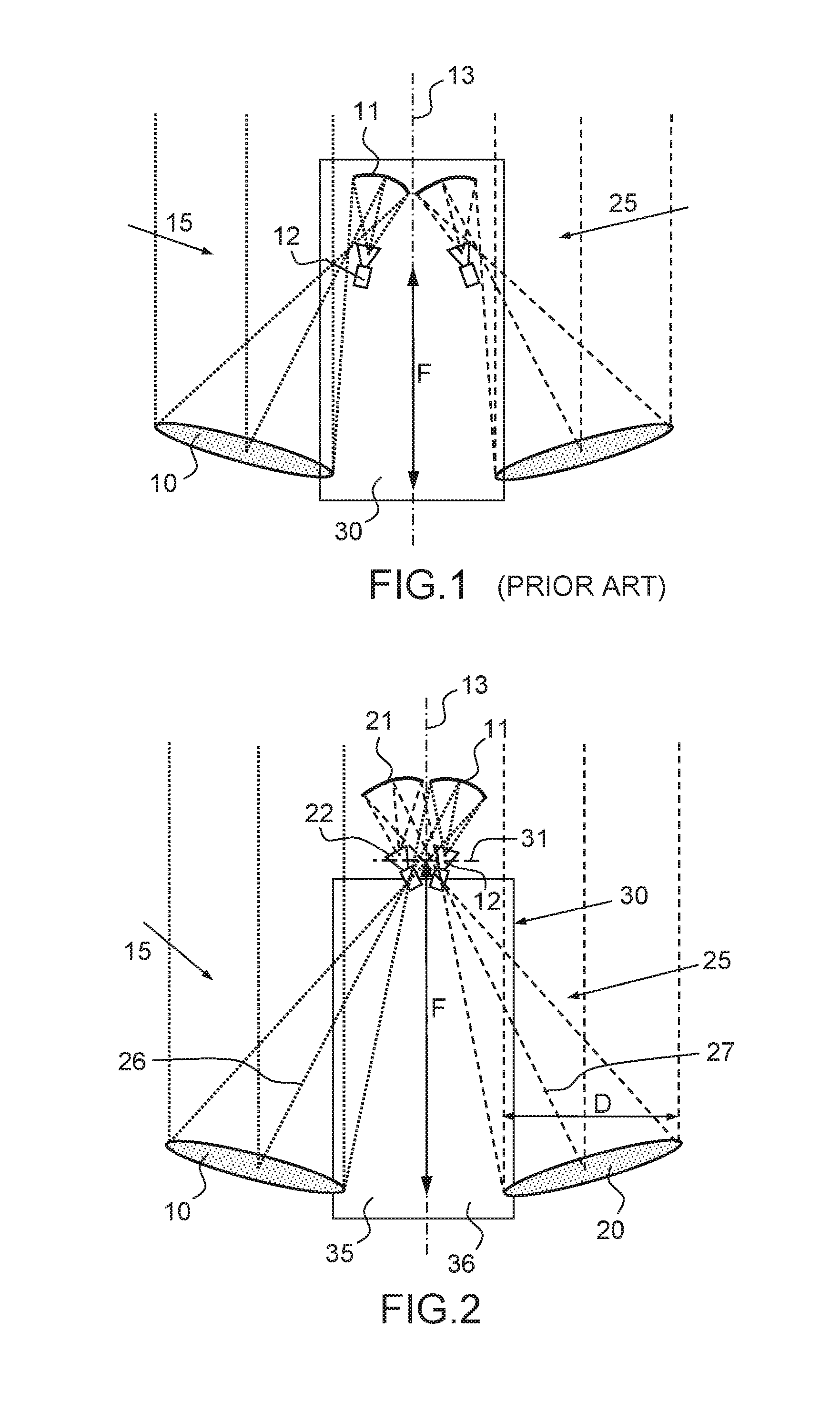
[0021]FIG. 2 shows an array of two twin-reflector antennas 15, 25, the two antennas being mounted on a common support 30, for example the same side of a satellite, the side of the satellite being able to be, for example, a lateral side or an Earth side of the satellite. Each antenna comprises a main reflector 10, 20, a secondary reflector 11, 21, and at least one radiating source 12, 22 illuminating the corresponding secondary reflector. The two antennas may have the same dimensions and the same focal length F, but this is not obligatory. Instead of being disposed on either side of a median line 13 of the common support 30, the two twin-reflector antennas 15, 25 criss-cross one another on the common support, thus enabling the main reflectors to be brought close to one another on the common support. As shown in FIG. 2, the optical paths 26, 27 of the beams produced by the two antennas criss-cross one another, the crossover point of the optical paths being located between the main ref...


PUM


Abstract

The two twin-reflector antennas comprise a common support on which they are mounted, with each twin-reflector antenna comprising a main reflector, a secondary reflector and at least one radiating source placed in front of the corresponding secondary reflector, and optical paths of beams produced by the two twin-reflector antennas crisscrossing one another.

Description

CROSS-REFERENCE TO RELATED APPLICATION[0001]This application claims priority to foreign French patent application No. FR 1400978, filed on Apr. 25, 2014, the disclosure of which is incorporated by reference in its entirety.FIELD OF THE INVENTION[0002]The present invention relates to an array of two twin-reflector antennas mounted on a common support and a satellite comprising this array. It applies to the domain of space applications and, in particular, to twin-reflector antennas with a long focal length which are intended to be installed on the same side of a satellite.BACKGROUND[0003]A twin-reflector antenna is comprised of a main reflector 10, a secondary reflector 11 and a radiating source 12 placed in front of the secondary reflector. The radiating source can operate in circular or linear monopolarization or bipolarization, in frequency monoband or frequency multiband mode. The radiating source 12 emits electromagnetic waves illuminating the secondary reflector 11 which reflect...

Claims


Application Information

Patent Timeline
Patent Type & Authority Patents(United States)
IPC IPC(8): H01Q19/18H01Q19/19H01Q21/00H01Q1/28
CPCH01Q19/18H01Q1/288H01Q19/19H01Q21/00H04B7/00
Inventor CARTAILLAC, ERWANPOUYEZ, STEPHANEMEDICI, DANIELBOFFELLI, STEPHANEGERARD, ALAIN
Owner THALES SA
Why Eureka
Try Eureka