Projection lens unit

a technology of projection lens and projection lens, which is applied in the direction of mountings, instruments, optics, etc., can solve the problems of degrading the quality of the image projected onto the screen, degrading the focal point of the projection lens system, and not achieving the desired amount of movemen

Active Publication Date: 2009-11-03
KONICA MINOLTA OPTO
View PDF10 Cites 10 Cited by
  • Summary
  • Abstract
  • Description
  • Claims
  • Application Information

AI Technical Summary

Benefits of technology

[0009]Temperature increases in the projection lens system act to increase the bark focal length. The back focal length is the distance, in the optical axis direction, from the lens closest to the image formation device among the plurality of lenses comprised by the projection lens system, to the focal point of the projection lens system. In other words, an increase in temperature of the projection lens system acts to shift the focal point of the projection lens system toward the rear-face side of the image formation device. On the other hand, a lens held by the movable lens barrel moves in the optical axis direction so as to recede from the image formation device as a result of thermal deformation of the thermal deformation member. Movement of a lens held by the lens barrel arising due to thermal deformation of the thermal deformation member acts so as to shift the focal point of the projection lens system toward the front-face side of the image formation device. Hence by moving the movable lens barrel holding the lens positioned closest to the image formation device by means of thermal deformation of the thermal deformation member, the shift in focal length of the projection lens system with an increase in temperature can be corrected.
[0010]The lens in the projection lens system which is closest to the image formation device and which tends to undergo temperature increases is moved by means of thermal deformation of the thermal deformation member. The thermal deformation member is placed in a position dose to the image formation device, so that the deformation amount at the time of temperature increase is large. Hence shifts in the focal length of the projection lens system at the time of temperature increase can be effectively corrected.
[0011]The lens barrel holding the lens is moved rather than the lens itself, and moreover thermal deformation of a thermal deformation member is utilized rather than thermal expansion of the lens itself so that digging into the lens barrel of the lens and lens deformation upon increases in temperature do not occur. Further, the lens can be maintained in a state of small inclination and eccentricity with respect to the lens barrel. Moreover, the lens itself need not be a irregular shape lens provided in a flange or similar, and construction is simple.
[0014]A projection lens unit of this invention comprises a movable lens barrel, which holds one or a plurality of lenses positioned closest to an image formation device and having positive power, and the movable lens barrel is caused to move in the optical axis direction relative to a holding tube by means of thermal deformation of a thermal deformation member at the time of an increase in temperature, so that the shift in focal length of the projection lens system accompanying the increase in temperature can effectively be corrected by means of a comparatively simple configuration.

Problems solved by technology

An increase in temperature causes a change in the refractive index of the materials comprised by lenses as well as thermal expansion of components comprising lenses, and it is known that, as a result, the focal point of the projection lens system may change, degrading the quality of the image projected onto the screen.
However, the configuration disclosed in Japanese Patent Laid-open No. 7-209609 (FIGS. 7 and 9) has the following problems.
First, the lens also expands in the radial direction with increases in temperature, and so if there is a difference in the thermal expansion coefficients of the lens and the lens barrel, the lens may dig into the lens barrel, so that the desired amount of movement is not obtained, and there is also the concern that the lens may be deformed.
Further, if the gap between lens barrel and lens is set to be large in order to prevent such digging-in, then the lens inclination and eccentricity are increased.
Also, complex irregular shape lens comprising a flange on the outer periphery are difficult and expensive to manufacture.
In particular, it is difficult to provide a flange in the case of a glass lens.
Thus the configuration disclosed in Japanese Patent Laid-open No. 7-209609 FIGS. 7 and 9) makes effective correction difficult, and entails a complex construction.
An anomalous dispersion lens having this positive power has large expansion and change in refractive index accompanying increases in temperature, and so is a major cause of fluctuations in the focal point of the projection lens system with rising temperature.

Method used


Image

  • Projection lens unit
  • Projection lens unit
  • Projection lens unit

Examples


first embodiment

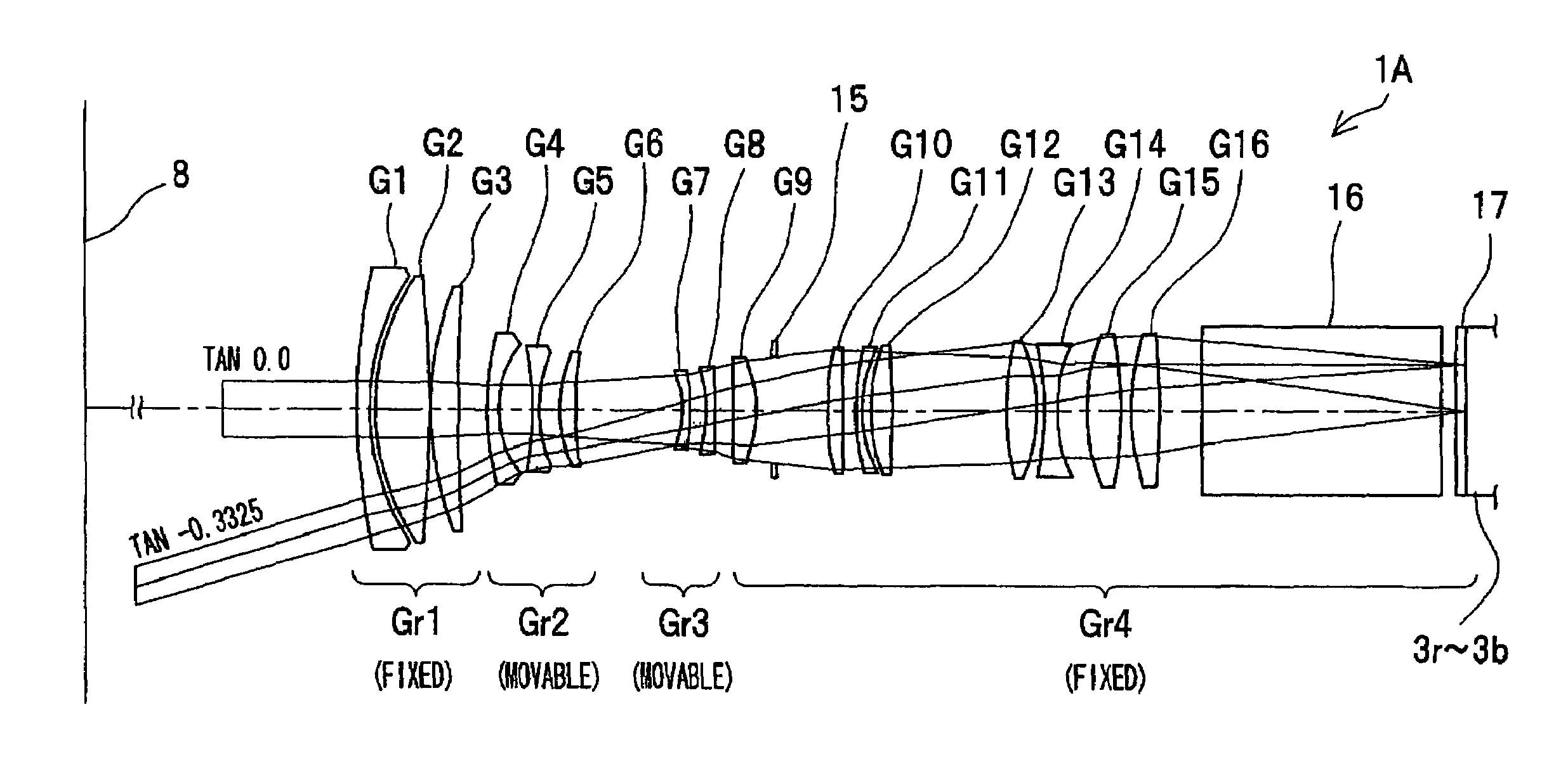
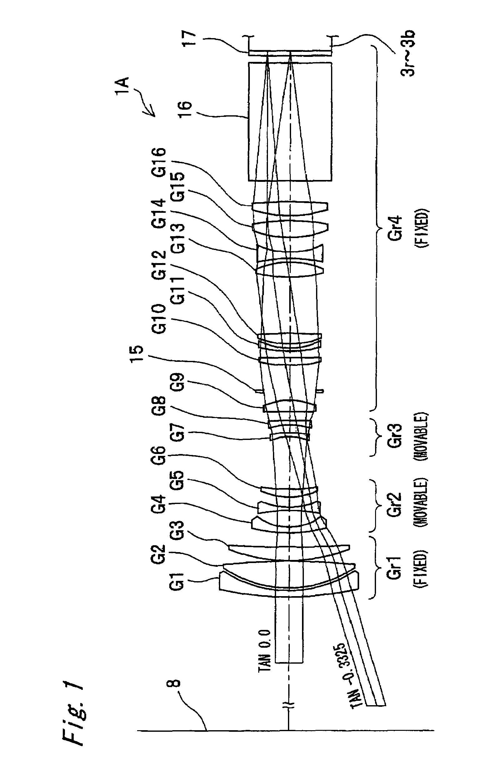
[0041]FIG. 1 shows the projection lens system 1A of a first aspect of the invention. This projection lens system 1A forms a portion of a front-projection type projector 2, shown in FIG. 4 through FIG. 6. A projection lens unit comprises the projection lens system 1A, and lens barrels, described below, which hold the lenses G1 to G16 of the projection lens system 1A (a fixed lens barrel 21, main lens barrel 22, and movable lens barrel 25). In addition to the projection lens system 1A, the projector 2 comprises, as a reflection-type image formation device, DMDs 3r, 3g, 3b, a light source 4, an illumination optical system 5, a color separation / combination prism 6, a total internal reflection prism 7, and a screen 8 (see FIG. 1).

[0042]In this aspect, the light source 4 comprises for example a light emission tube 11 which is a xenon lamp, and an elliptical reflector 12. The illumination optical system 5 comprises a rod integrator 13 and a relay lens group 14; light emitted from the light...

second embodiment

[0081]FIG. 17 and FIG. 18 show the projection lens system 1B of a second aspect of the invention. This projection lens system 1B forms a portion of a projector 2, similarly to the case of the first aspect, and similarly to the first aspect comprises a light source 4, illumination optical system 5, color separation / combination prism 6, total internal reflection prism 7, and screen 8 (see FIG. 4 to FIG. 6).

[0082]The projection lens system 1B comprises 16 lenses G1 to G16 and a diaphragm 15, and has telecentric properties. The radii of curvature of the lenses G1 to G16, the distances on the optical axis between the lens surfaces r1 to r39 of the lenses G1 to G16, the refractive indices N1 to N20, and the Abbe numbers ν1 to ν20, are as indicated in Table 5 and Table 6 below.

[0083]

TABLE 5DISTANCE BETWEENRADIUS OFSURFACES ONABBEOPTICAL ELEMENTCURVATUREOPTICAL AXISREFRACTIVE INDEXNUMBERLENS G1r1: 99.180—d1: 11.431N1: 1.58913ν1: 61.25r2: 11824.525d2: 1.851LENS G2r3: 108.956(ANOMALOUSd3: 4.1...

third embodiment

[0093]FIG. 21 shows the projection lens system 1C of a third aspect of the invention. This projection lens system 1C forms a portion of a projector 2, similarly to the case of the first aspect, and similarly to the first aspect comprises a light source 4, illumination optical system 5, color separation / combination prism 6, total internal reflection prism 7, and screen 8 (see FIG. 4 to FIG. 6).

[0094]The projection lens system 1C comprises 17 lenses G1 to G17 and a diaphragm 15, and has telecentric properties. The radii of curvature of the lenses G1 to G17, the distances on the optical axis between the lens surfaces r1 to r39 of the lenses G1 to G17, the refractive indices N1 to N19, and the Abbe numbers ν1 to ν19, are as indicated in Table 7 and Table 8 below.

[0095]

TABLE 7DISTANCE BETWEENRADIUS OFSURFACES ONABBEOPTICAL ELEMENTCURVATUREOPTICAL AXISREFRACTIVE INDEXNUMBERLENS G1r1: 249.283—d1: 5.000N1: 1.64769ν1: 33.84r2: 108.596d2: 2.324LENS G2r3: 111.490d3: 11.725N2: 1.60311ν2: 60.69r...


PUM


Abstract

A projection lens system 1A enlarges and projects onto a screen 8, via a plurality of lenses G1 to G16, image light emitted from, a light source 4 and modulated by DMDs 3r to 3b. A movable lens barrel 25 holds the lens G16, having positive power, which is positioned closest to the DMDs 3r to 3b. An outer tube 24 holds the movable lens barrel 25 to enable movement in the optical axis direction. Through thermal deformation at the time of an increase in temperature, the bimetal member 27 moves the movable lens barrel 25 in the optical axis direction so as to recede from the image formation devices which are the DMDs 3r to 3b.

Description

RELATED APPLICATION[0001]This application is based on Japanese Patent Applications No. 2006-84078 and 2006-174051 the contents in which are incorporated herein by reference.BACKGROUND OF THE INVENTION[0002]The present invention relates to a projection lens unit, comprising a projection lens system which enlarges and projects image light from an image formation device onto a screen and a lens barrel which holds lenses of the projection lens system. In particular the present invention relates to correction of the focal point of the projection lens system when the temperature rises in the projection lens unit.[0003]As projection-type image display devices, projectors comprising DMDs (Digital Micromirror Devices) and other reflection-type image formation devices, and which enlarge and project onto a screen an image appearing on the image formation device by means of a projection lens system comprising a plurality of lenses, are well-known. Because in large-size projectors for use in cin...

Claims


Application Information

Patent Timeline
Patent Type & Authority Patents(United States)
IPC IPC(8): G02B7/02
CPCG02B7/023G02B13/22G02B7/028
Inventor MASUI, ATSUOMATSUDA, TOKUJIWATARU, KOHEI
Owner KONICA MINOLTA OPTO
Why Eureka
Try Eureka