Transfer apparatus, server, and route changing method

a transfer apparatus and a server technology, applied in the direction of electrical apparatus, digital transmission, data switching networks, etc., can solve the problems of increasing control load and unstable control of communication networks, and achieve the effect of reducing the load of controlling communication networks

Active Publication Date: 2017-03-07
HITACHI LTD
View PDF9 Cites 0 Cited by
  • Summary
  • Abstract
  • Description
  • Claims
  • Application Information

AI Technical Summary

Benefits of technology

[0005]It is an object of this invention to reduce the load of controlling communication networks, which is incurred by the migration of services.

Problems solved by technology

Control load therefore increases as the switching of communication networks takes place, which makes control of the communication networks unstable in the migration of services.

Method used


Image

  • Transfer apparatus, server, and route changing method
  • Transfer apparatus, server, and route changing method
  • Transfer apparatus, server, and route changing method

Examples


first embodiment

System Configuration Example

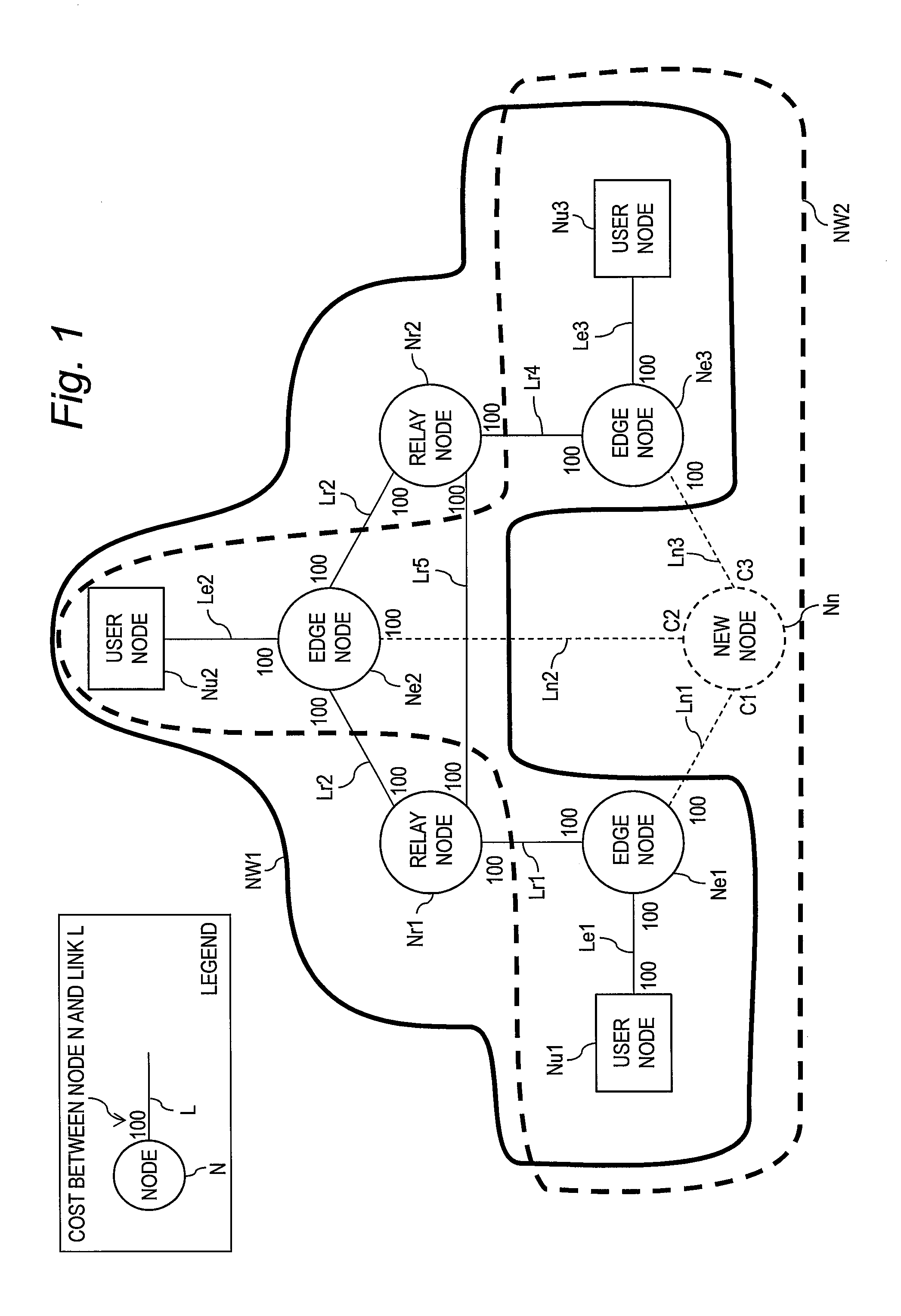
[0037]FIG. 1 is an explanatory diagram illustrating a system configuration example of a communication system according to a first embodiment of this invention. The communication system is a system in which a plurality of nodes as transfer apparatus for transferring data are coupled in a manner that allows communication to and from one another, and constitutes a network NW1. The nodes include user nodes Nu# (# represents a numeral), edge nodes Ne#, relay nodes Nr#, and new nodes Nn. Those nodes are collectively referred to as nodes N.

[0038]The edge nodes Ne# and the relay nodes Nr# are collectively referred to as edge nodes Ne and relay nodes Nr, respectively. The solid lines and dotted lines between the nodes N represent lines for transporting data, which are also referred to as links. The links include links Le# between the edge nodes Ne and the user nodes Nu, links Lr# between the relay nodes Nr and the edge nodes Ne, links Lr# between the relay nodes N...

second embodiment

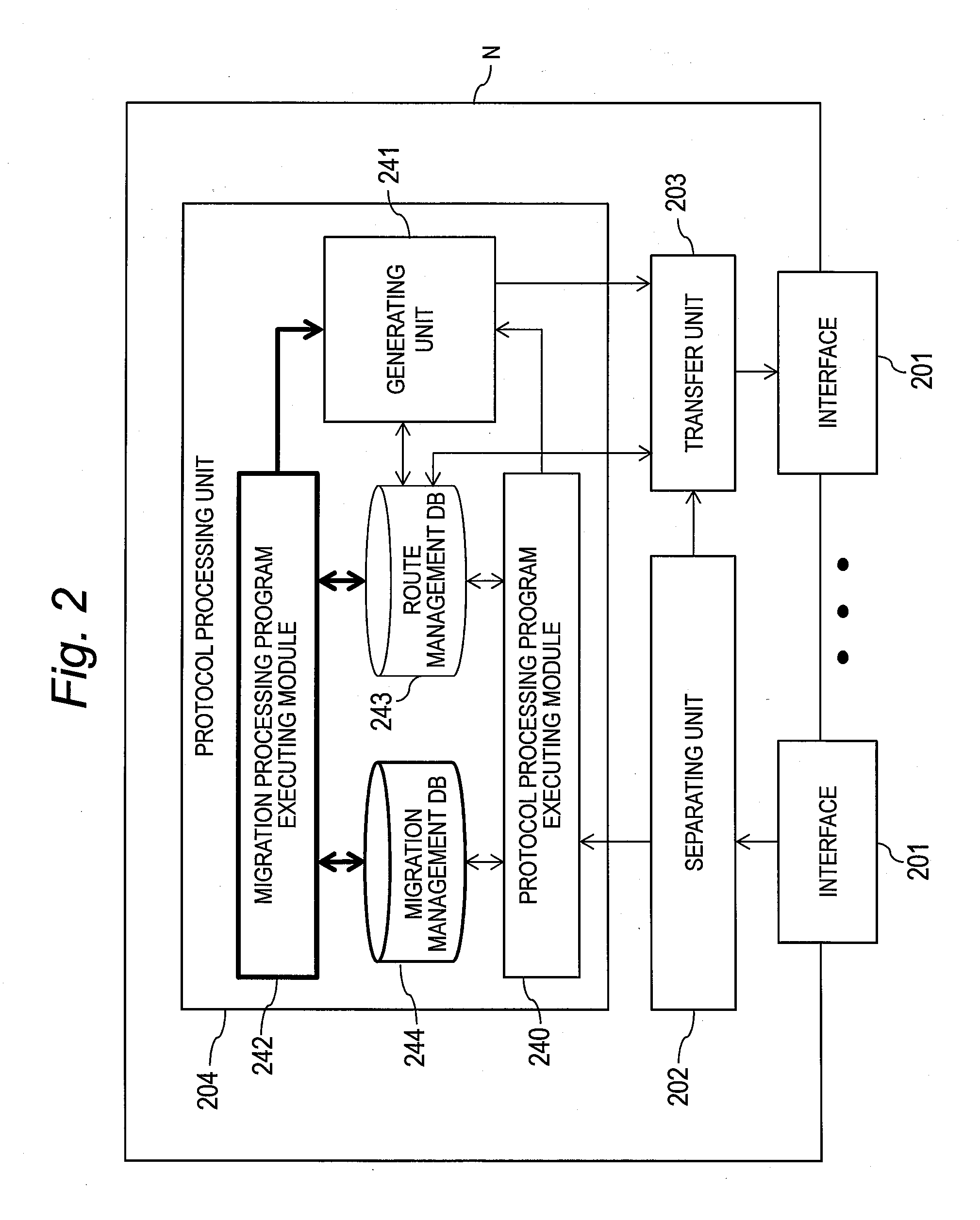
[0114]A second embodiment of this invention describes a mode in which a part of each node N is separated from the rest. The nodes N in the first embodiment are configured as illustrated in FIG. 2. In the second embodiment, the protocol processing units 204 included in the respective nodes N in the first embodiment are extracted from the nodes N to constitute one protocol processing server, thereby giving the nodes N of the second embodiment a configuration that does not include a protocol processing unit. The protocol processing server and the nodes N are coupled to each other in a manner that allows communication between the server and the nodes. The description of the second embodiment focuses on differences from the first embodiment. In the second embodiment, components that are the same as those in the first embodiment are denoted by the same reference symbols, and descriptions thereof are omitted.

[0115]FIG. 17 is a block diagram illustrating a configuration example of each node...

third embodiment

[0121]A third embodiment of this invention deals with an example in which the cost management table 500 according to the first embodiment and the second embodiment further includes band information. The band information is information that includes a logical bandwidth used by a label-switched path (LPS) and the priority level of the LSP. The description of the third embodiment focuses on differences from the first embodiment and the second embodiment. In the third embodiment, components that are the same as those in the first embodiment and the second embodiment are denoted by the same reference symbols, and descriptions thereof are omitted.

[0122]FIG. 19 is a table showing an example of what is stored in the cost management table 500 according to the third embodiment. The cost management table 500 includes, in addition to the information shown in FIG. 5, an LSP field (“LSP”) 1901, a used bandwidth field (“Bandwidth”) 1902, and a priority field (“Priority”) 1903 as fields for storing...


PUM


Abstract

A transfer apparatus is configured to: calculate a total cost of a first route in a first network that starts from a source transfer apparatus and ends at a destination transfer apparatus; obtain a particular cost being a cost between the source transfer apparatus and a first line, which couples the source transfer apparatus and its own transfer apparatus, in a second route, which starts from the source transfer apparatus and reaches the destination transfer apparatus via its own transfer apparatus; calculate a differential between the total cost and the particular cost; set, based on the differential, a cost between its own transfer apparatus and a second line, which couples its own transfer apparatus and the destination transfer apparatus, to a value that causes the source transfer apparatus to select the second route rather than the first route; and notify the cost value to the source transfer apparatus.

Description

CLAIM OF PRIORITY[0001]The present application claims priority from Japanese patent application JP 2013-244825 filed on Nov. 27, 2013, the content of which is hereby incorporated by reference into this application.BACKGROUND OF THE INVENTION[0002]This invention relates to a transfer apparatus for transferring data, a server, and a route changing method.[0003]There has hitherto been a communication route changing method in which planes (communication routes) are switched / returned to their original roles during a network failure or network maintenance (JP 2006-148497 A). In this communication route changing method, a communication system includes a first router and a second router, which constitute one virtual router protocol group and which can both dynamically change from an active router to a standby router, or from a standby router to an active router. When a first port of the first router is opened to hold communication to and from a first device and a second port of the second r...

Claims


Application Information

Patent Timeline
Patent Type & Authority Patents(United States)
IPC IPC(8): H04L12/721H04L12/707H04L45/02H04L45/24
CPCH04L45/123H04L45/22
Inventor SHIBATA, TAKESHIKITANI, MAKOTOSUZUKI, TOSHIAKI
Owner HITACHI LTD
Why Eureka
Try Eureka