Heat transfer tube expansion apparatus

a technology of heat transfer tube and expansion apparatus, which is applied in the direction of heat exchanger fastening, lighting and heating apparatus, tubular elements, etc., can solve the problems of axial direction length of portions, easy variation, and the inability to perform precise, so as to achieve smooth operation

Active Publication Date: 2017-03-14
DAIKIN IND LTD
View PDF17 Cites 6 Cited by
  • Summary
  • Abstract
  • Description
  • Claims
  • Application Information

AI Technical Summary

Benefits of technology

[0006]The problem of the present invention is to provide a heat transfer tube expansion apparatus and a heat transfer tube expansion method where it is possible to apply to a case where the intervals between heat transfer tubes are narrow and it is possible to smoothly perform precise tube expansion by suppressing variation in the force with which the heat transfer tubes are grasped.
[0008]Here, tube expansion with the mandrels is performed in a state which is the first state where the moving section covers the surroundings of the grasping sections as described above. For this reason, the outer surfaces of the heat transfer tubes abut with the inner surfaces of the grasping sections and the outer surfaces of the grasping sections abut with the inner surfaces of the moving section. That is, there is a state where the moving section overlaps with the grasping sections which grasp the one end sections of the heat transfer tubes when the grasping sections fix the heat transfer tubes so as not to move in the axial direction. Due to this, here, variation in the force with which the heat transfer tubes are grasped by the grasping sections is suppressed and it is possible to perform precise tube expansion compared to fixing of the heat transfer tubes using the tube abutting members and the guide cylinders in the background art. In addition, here, it is possible to shorten the axial direction length of portions, which are grasped by the grasping sections out of the one axial direction end sections of the heat transfer tubes, since it is possible for the force with which the heat transfer tubes are grasped by the grasping sections to be larger and it is possible to also contribute to increased compactness of a heat exchanger compared to fixing of the heat transfer tubes using the tube abutting members and the guide cylinders in the background art. Moreover, here, it is possible to also apply to a case where the intervals between the heat transfer tubes are narrow since it is possible for the moving section to switch to the first state of covering the surroundings of the grasping sections only by moving in the axial direction of the heat transfer tubes. Furthermore, here, different to tube expansion which accompanies a guide cylinder moving process in the background art, it is possible to smoothly perform tube expansion since it is possible to perform a tube expansion process as a single process while fixing the heat transfer tubes so as not to move in the axial direction.
[0018]Here, it is possible to secure a tooling allowance in the thickness of the tube during tube expansion to be secured at the one end sections of the heat transfer tubes which are grasped by the grasping sections.
[0020]Here, it is possible for the one end sections of the heat transfer tubes to be smoothly guided to the grasping sections when the grasping sections are arranged at the one end sections of the heat transfer tubes.
[0022]Here, it is possible to smoothly perform an operation where the moving section switches from the second state to the first state.
[0024]Here, as described above, tube expansion with the mandrels is performed in a state which is the first state where the moving section covers the surroundings of the grasping sections. For this reason, the outer surfaces of the heat transfer tubes abut with the inner surfaces of the grasping sections and the outer surfaces of the grasping sections abut with the inner surfaces of the moving section. That is, there is a state where the moving section overlaps with the grasping sections which grasp the one end section of the heat transfer tubes when the grasping sections fix the heat transfer tubes so as not to move in the axial direction. Due to this, here, variation in the force with which the heat transfer tubes are grasped by the grasping sections is suppressed and it is possible to perform precise tube expansion compared to fixing of the heat transfer tubes using the tube abutting members and the guide cylinders in the background art. In addition, here, it is possible to shorten the axial direction length of portions, which are grasped by the grasping sections out of the one axial direction end sections of the heat transfer tubes, since it is possible for the force with which the heat transfer tubes are grasped by the grasping sections to be large and it is possible to also contribute to increased compactness of a heat exchanger compared to fixing of the heat transfer tubes using the tube abutting members and the guide cylinders in the background art. Moreover, here, it is possible to also apply to a case where the intervals between the heat transfer tubes are narrow since it is possible for the moving section to switch to the first state of covering the surroundings of the grasping sections only by moving in the axial direction of the heat transfer tubes. Furthermore, here, different to tube expansion which accompanies a guide cylinder moving process in the background art, it is possible to smoothly perform tube expansion since it is possible to fix the heat transfer tubes so as not to move in the axial direction and to perform a tube expansion process as a single process.

Problems solved by technology

However, in the heat transfer tube expansion apparatus and the heat transfer tube expansion method in the background art described above, there is a concern that it is easy for variation to occur in the force with which the heat transfer tubes are grasped by the grasping sections since the guide cylinders move to only in front of the grasping sections and that it is not possible to perform precise tube expansion.
In addition, the axial direction length of portions, which are grasped by the grasping sections out of the one axial direction end sections of the heat transfer tubes, becomes longer since it is not possible for the force with which the heat transfer tubes are grasped to be large.
In addition, it is not possible to perform smooth tube expansion since the tube expansion process is divided into two steps with a guide cylinder moving process in-between.
In addition, even though moving of the guide cylinders which number as many as the number of the heat transfer tubes is necessary at this time, it is difficult to provide the plurality of guide cylinders to correspond to the plurality of heat transfer tubes in a case where the intervals between the heat transfer tubes are extremely narrow or a case where the intervals between the heat transfer tubes are an unequal pitch where the intervals are not equal.

Method used


Image

  • Heat transfer tube expansion apparatus
  • Heat transfer tube expansion apparatus
  • Heat transfer tube expansion apparatus

Examples


Embodiment Construction

[0041]An embodiment of a heat transfer tube expansion apparatus and a heat transfer tube expansion method according to the present invention will he described below based on the diagrams. Here, specific examples of the heat transfer tube expansion apparatus and the heat transfer tube expansion method according to the present invention are not limited to the embodiment and modified examples described below and modifications are possible within a scope which does not depart from the gist of the invention.

[0042](1) Overall Configuration of Heat Transfer Tube Expansion Apparatus

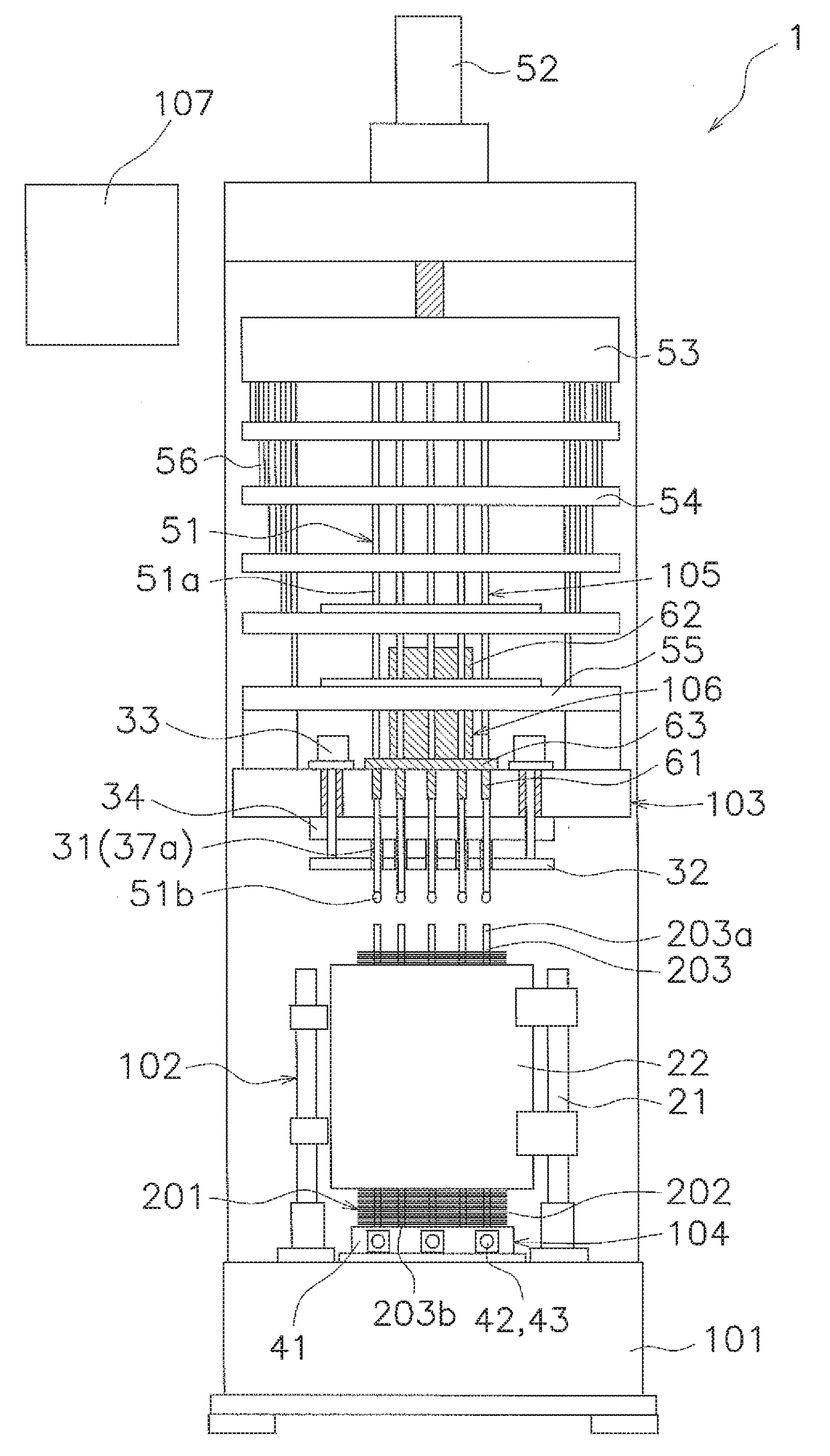
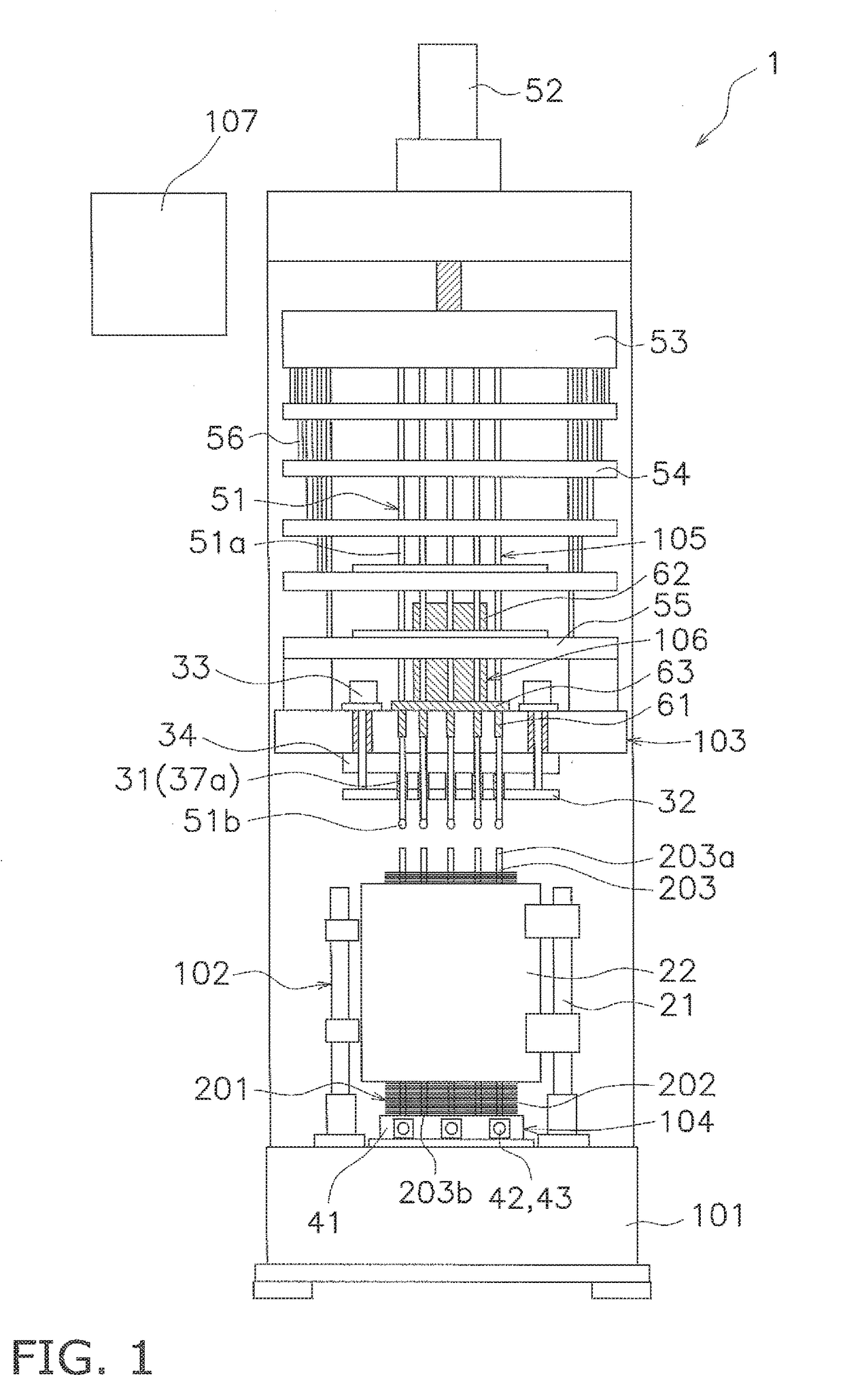
[0043]FIG. 1 is a schematic configuration diagram of a heat transfer tube expansion apparatus 1 according to one embodiment of the present invention.

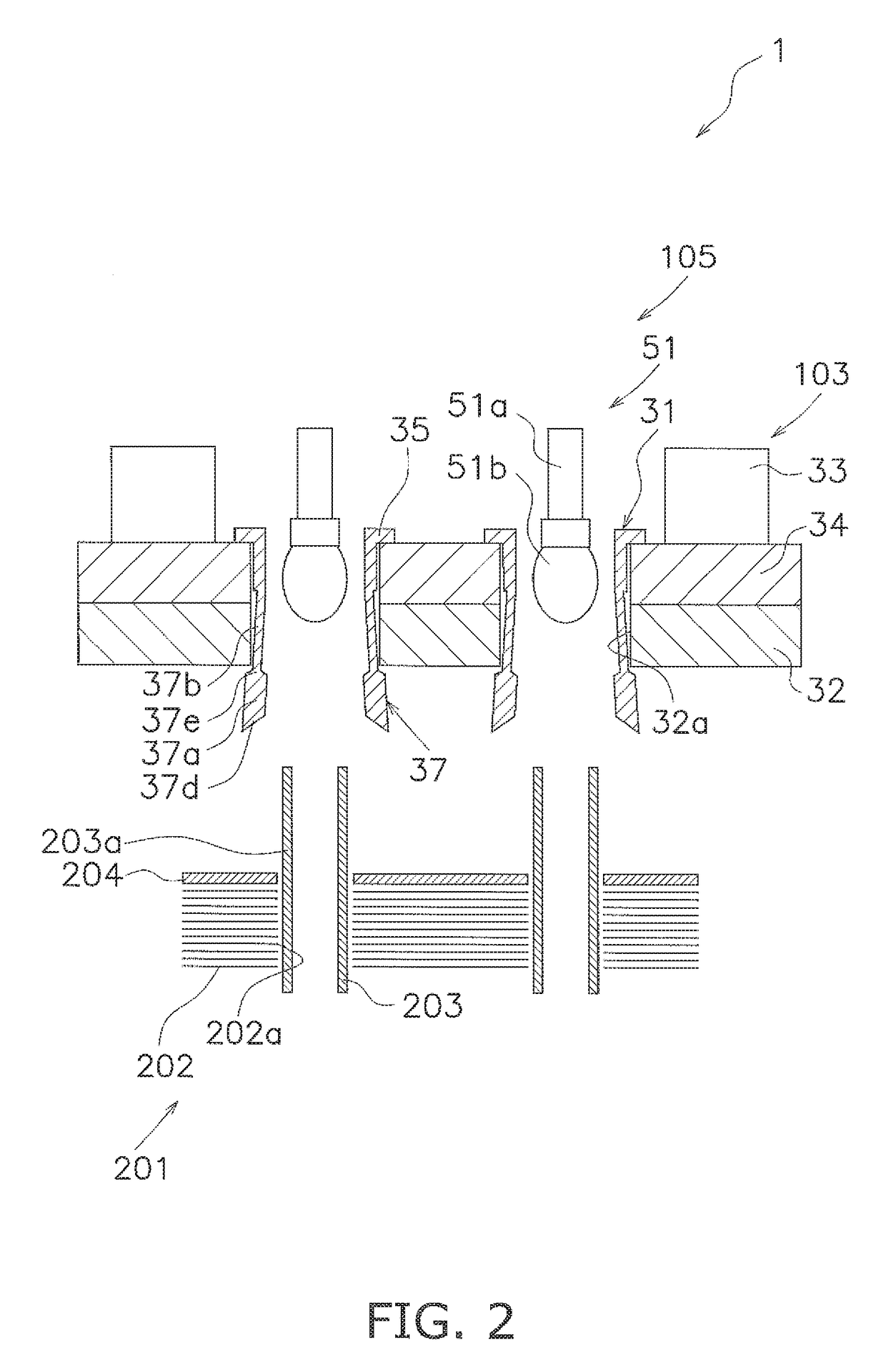
[0044]The heat transfer tube expansion apparatus 1 is an apparatus for expansion of a plurality of heat transfer tubes 203 in a state of being inserted in insertion holes 202a in a plurality of heat transfer fins 202 (refer to FIG. 2) which are layered with spacing o...


PUM

PropertyMeasurementUnit
forceaaaaaaaaaa
lengthaaaaaaaaaa
inner diameteraaaaaaaaaa

Abstract

A heat transfer tube fixing apparatus of a heat transfer tube expansion apparatus has grasping sections and a moving section. The grasping sections grasp one axial direction end sections of a plurality of heat transfer tubes in a state where the heat transfer tubes are inserted in a plurality of heat transfer fins. The moving section switches between a first state of covering the surroundings of the grasping sections and a second state of not covering the surroundings of the grasping sections by moving in the axial direction of the heat transfer tubes. The grasping sections fix the heat transfer tubes so as not to move in the axial direction and the heat transfer fins and the heat transfer tubes are fixed by the heat transfer tubes expanding in a state where the moving section is in the first state.

Description

CROSS-REFERENCE TO RELATED APPLICATIONS[0001]This U.S. National stage application claims priority under 35 U.S.C. §119(a) to Japanese Patent Application No. 2013-136404, filed in Japan on Jun. 28, 2013, the entire contents of which are hereby incorporated herein by reference.TECHNICAL FIELD[0002]The present invention relates to a heat transfer tube expansion apparatus and a heat transfer tube expansion method and particularly relates to a heat transfer tube expansion apparatus and a heat transfer tube expansion method where a plurality of heat transfer tubes expand in a state of being inserted in insertion holes in a plurality of heat transfer fins which are layered with spacing of a predetermined interval.BACKGROUND ART[0003]In the background art, there is a heat transfer tube expansion apparatus and a heat transfer tube expansion method where a plurality of heat transfer tubes expand in a state of being inserted in insertion holes in a plurality of heat transfer fins which are lay...

Claims


Application Information

Patent Timeline
Patent Type & Authority Patents(United States)
IPC IPC(8): B23P15/26B21D39/20F28F1/32B21D41/02B21D53/08
CPCB23P15/26B21D39/20B21D41/02B21D53/085F28F1/32F28F2275/125Y10T29/4938Y10T29/4994Y10T29/49368Y10T29/49375Y10T29/49391Y10T29/53117Y10T29/53122
Inventor TANAKA, YOSHIKAZUKATAKAMI, TAKUROU
Owner DAIKIN IND LTD
Why Eureka
Try Eureka