Apparatus and method for carrying out a plasma deposition process

a plasma deposition and apparatus technology, applied in the field of apparatus and methods for carrying out plasma deposition processes, can solve the problems of complex system construction and maintenance, non-uniform thickness and refractive index of axial deposition, adversely affecting fiber quality parameters such as attenuation, mode field width uniformity, bandwidth uniformity, etc., to reduce the deviation of thickness and/or refractive index

Active Publication Date: 2017-03-14
DRAKA COMTEQ BV
View PDF6 Cites 0 Cited by
  • Summary
  • Abstract
  • Description
  • Claims
  • Application Information

AI Technical Summary

Benefits of technology

[0057]A key to the present invention is a short interruption of at least one of the secondary gas flows during one or more strokes in order to reduce deviations in the thickness and / or refractive index in axial direction of the preform obtained. The invention allows to actively influence the refractive index of the preform at every given axial position.

Problems solved by technology

This system is complicated to build and maintain.
Such axial microwave power non-uniformity can cause axial deposition thickness and refractive index non-uniformity, which adversely affects fiber quality parameters such as attenuation, mode field width uniformity, and bandwidth uniformity.

Method used


Image

  • Apparatus and method for carrying out a plasma deposition process
  • Apparatus and method for carrying out a plasma deposition process
  • Apparatus and method for carrying out a plasma deposition process

Examples


example 1

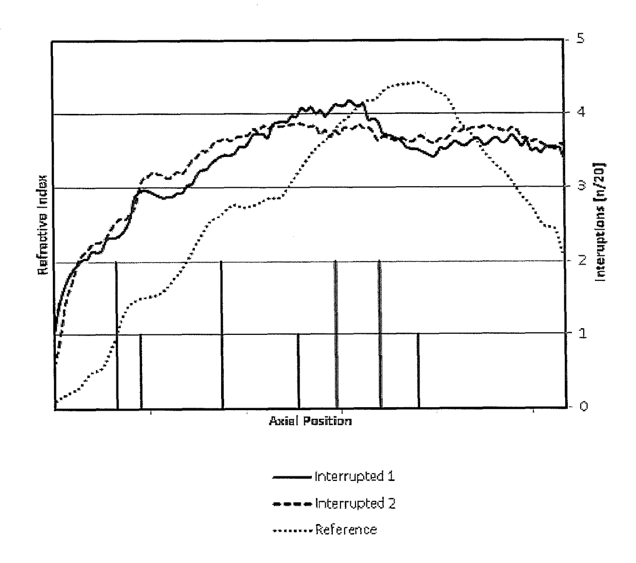
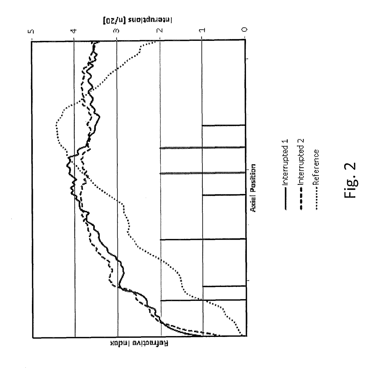
[0141]The same PCVD process as in Comparative Example 1 was used, with this difference that the flow of GeCl4 was interrupted during a fraction of the passes. It should be noted that the main gas flow was not interrupted. The number and axial position of the start of these interruptions per 20 passes is shown in FIG. 2.

[0142]The substrate tube thus obtained was formed into a solid rod in the same manner as in comparative example 1. The solid line ‘interrupted 1’ in FIG. 2 shows the difference of the refractive index between the core layers and the cladding layers as a function of the length of the primary preform.

[0143]This was repeated to obtain a second solid rod. The striped line ‘interrupted 2’ in FIG. 2 shows the difference of the refractive index between the core layers and the cladding layers as a function of the length of the primary preform.

example 2

[0145]The same PCVD process as in Comparative Example 2 was used, with the difference that the flow of GeCl4 was interrupted at several axial positions (9 or 10 times) during each forward stroke for a total of 10 passes (each comprising a forward and back stroke). The backwards strokes were not interrupted. In other words, 50% of the strokes comprised interruptions.

[0146]The duration of one forward stroke is 4 seconds, the duration of one backward stroke is 4 seconds, the duration of each of the interruptions is 80 milliseconds. In total, there are 10 forward strokes and 10 backward strokes (total time: 80 seconds) and 96 interruptions (total time: 7.68 seconds). The time of the interruption during a stroke has a duration of 9.6% of the total time of said stroke.

[0147]It should be noted that the main gas flow was not interrupted. The number and axial position of the start of these interruptions is shown in FIG. 3. Therefore, one or more aims of the present invention mentioned above ...


PUM

PropertyMeasurementUnit
control frequencyaaaaaaaaaa
pressureaaaaaaaaaa
pressureaaaaaaaaaa

Abstract

A method for carrying out a plasma deposition process including the steps of providing a substrate tube, supplying dopant-containing glass-forming gases to the substrate including a main gas flow and one or more secondary gas flows, inducing a plasma in the substrate tube, moving a reaction zone back and forth in strokes between a reversal point near the supply side and a reversal point near the discharge side, and interrupting the secondary gas flow during a portion of each stroke, each interruption having a start point and an end point within the same stroke.

Description

TECHNICAL FIELD AND BACKGROUND OF THE INVENTION[0001]The present invention relates a method for carrying out a plasma deposition process including the steps of:[0002]i) providing a hollow substrate tube;[0003]ii) supplying a supply flow of dopant-containing glass-forming gases to the substrate tube of step i), wherein the supply flow comprises a main gas flow and one or more secondary gas flows, preferably said main gas flow mainly comprising the glass-forming gases and said one or more secondary gas flows mainly comprising precursors for dopant(s);[0004]iii) inducing a plasma by means of electromagnetic radiation in at least a part of the substrate tube of step ii) to create a reaction zone in which deposition of one or more glass layers onto the interior surface of the substrate tube takes place;[0005]iv) moving the reaction zone back and forth in longitudinal direction over the substrate tube between a reversal point located near the supply side and a reversal point located near ...

Claims


Application Information

Patent Timeline
Patent Type & Authority Patents(United States)
IPC IPC(8): C03B37/018C23C16/40C23C16/04C23C16/511
CPCC03B37/0183C03B37/018C23C16/045C23C16/401C23C16/511C03B2201/31C03B2201/12C03B37/01807C03B37/01846C03B37/01892C03B2203/16
Inventor MILICEVIC, IGORVAN STRALEN, MATTHEUS JACOBUS NICOLAASHARTSUIKER, JOHANNES ANTOONKRABSHUIS, GERTJAN
Owner DRAKA COMTEQ BV
Why Eureka
Try Eureka