Remote operated safety attendant

a safety attendant and remote control technology, applied in the direction of traffic control of road vehicles, traffic signals, controlling traffic signals, etc., can solve the problems of high number of injuries and deaths of traffic control workers per year, and the danger of controlling traffic from the roadway or adjacent to the roadway, so as to achieve the effect of high number of injuries and deaths

Inactive Publication Date: 2017-03-21
WILLIAMS JOHN SL
View PDF17 Cites 14 Cited by
  • Summary
  • Abstract
  • Description
  • Claims
  • Application Information

AI Technical Summary

Benefits of technology

[0017]The remote operated safety attendant disclosed herein provides a user friendly, durable, highly visible and safe to use remote controlled traffic control signaling device. The most common method for traffic control workers to control traffic flow patterns at a construction work site, or under similar situations, is to stand on or adjacent to roadway and display a handheld sign to oncoming traffic. The most common signage has STOP displayed on one side and SLOW displayed on the second side. The use of traffic control workers, to date, has been the preferred methodology for controlling traffic flow patterns because of the ability of the worker to quickly make decisions on how to control traffic in direct response to the situation and in response to the actions of motorists. As indicated, however, controlling traffic from the roadway or adjacent to the roadway is very dangerous with a high number of injuries and deaths per year to these traffic control workers.
[0021]In use, it is preferred that a worker be positioned near the device but away from the roadway so that the worker can visualize traffic patterns and make quick decisions responsive to the environment as to whether to slow or stop oncoming traffic. This allows the benefits of human control of signaling devices while gaining the benefit of a robotic signal device to limit or control the likelihood of injury or even death to workers.

Problems solved by technology

As indicated, however, controlling traffic from the roadway or adjacent to the roadway is very dangerous with a high number of injuries and deaths per year to these traffic control workers.

Method used


Image

  • Remote operated safety attendant
  • Remote operated safety attendant
  • Remote operated safety attendant

Examples


Embodiment Construction

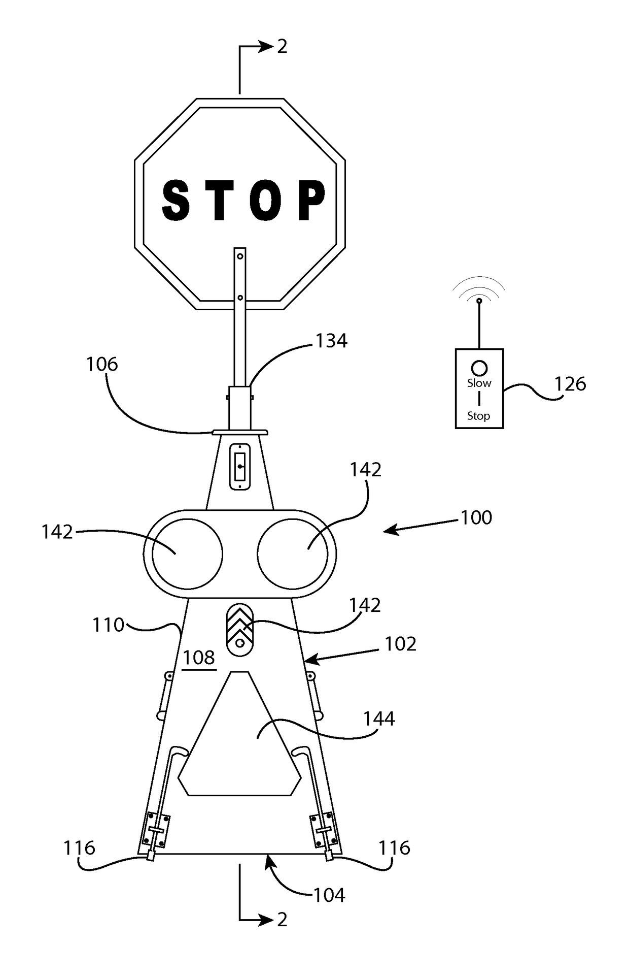
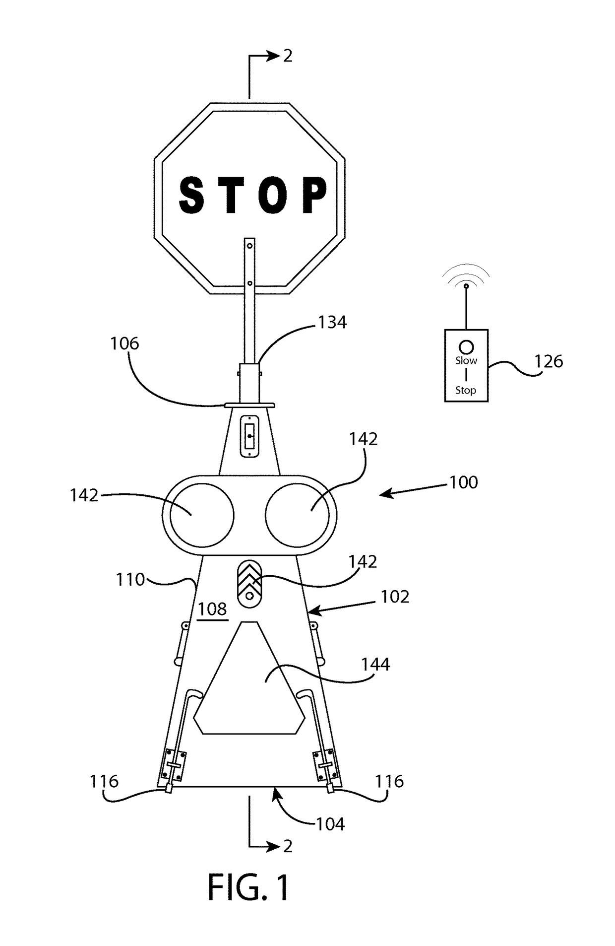
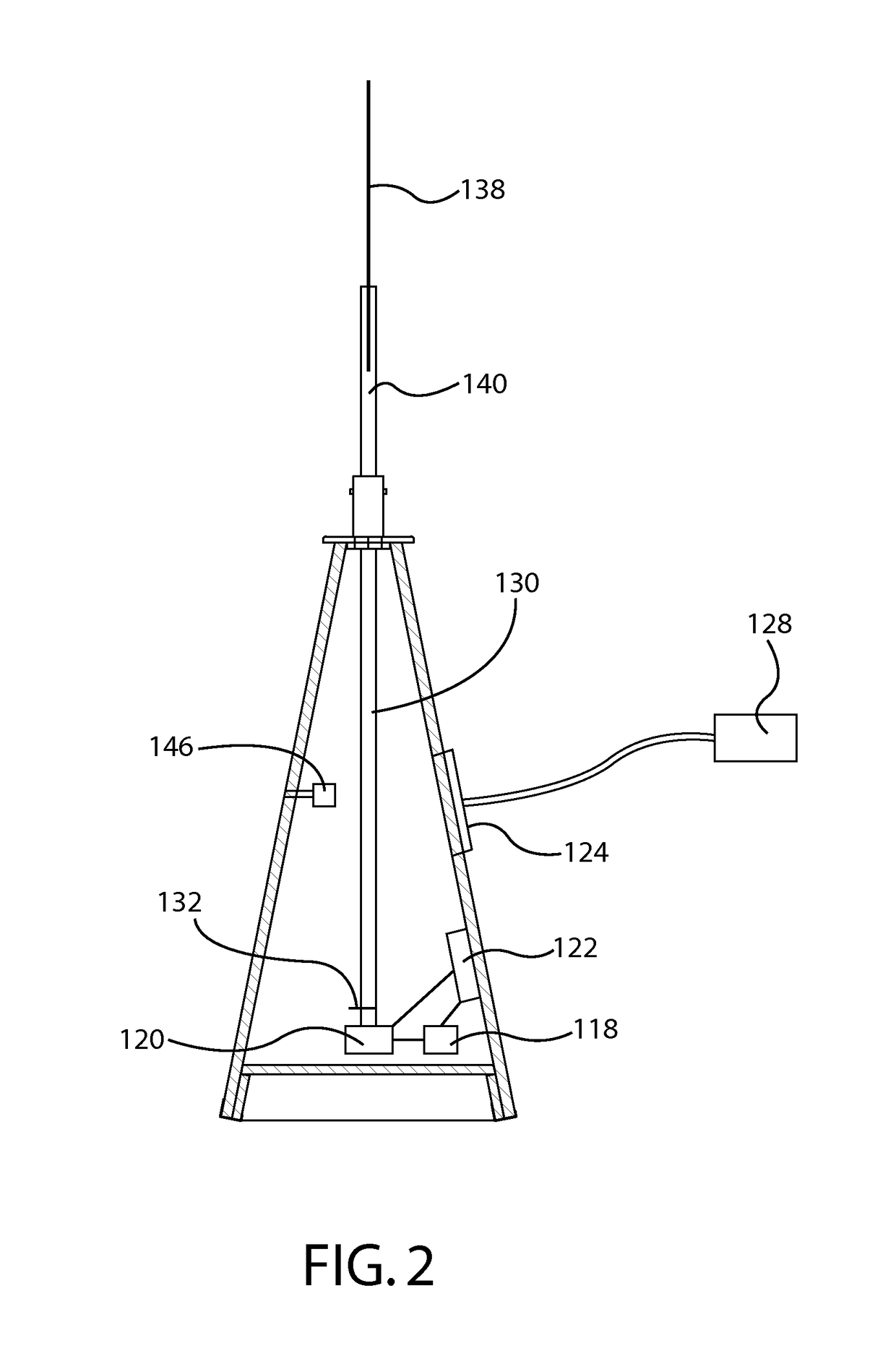
[0029]Referring now generally to FIGS. 1 through 4, the inventive device 100 includes a housing 102 that is preferably pyramidic in shape. The housing 102 has a base 104, a spaced-apart top 106 and four sides 108 tapering between the base 104 and top 106. The sides 108 meet at corners 110 that may be beveled or rounded to limit straight or “cutting” edges. The housing 102 might also be provided in a round, or other geometric shape if desired. The preferred shape, however, includes flat or planar sides 108 as shown in the figures due to the specific impact safety imparted by that configuration.

[0030]The housing 102 is preferably made of manufactured dense fiber (MDF) but can also be manufactured high impact plastic, fiberglass or resin compound that are easily moldable, can be colored and is durable. It should be apparent that other materials could be used to manufacture the housing 102 but doing so affects the crashworthiness and safety of the device. Moreover, it is preferred that ...


PUM


Abstract

A remote operated safety attendant having a substantially pyramidic housing made of high impact material such as manufactured dense fiber. A two sided sign is mounted to a shaft positioned within the housing and connected to a drive motor and a remote signal receiver. A remote signal sender is used to send signals to the receiver to selectively actuate the drive mechanism which rotates to alternately display the opposed sides of the sign. The device meets requisite traffic safety requirements and allows an operator to remotely control the device to remain out of the pathway of vehicles that they are controlling through the signaling device.

Description

RELATED APPLICATION[0001]This application claims the benefit of U.S. Provisional Patent Application 61 / 537,925 filed Sep. 22, 2011, the entire contents of which are incorporated herein by reference.FIELD OF THE INVENTION[0002]The present invention relates to a remote controlled traffic signal system which allows an operator to alternate the orientation of a traffic sign from a remote location wherein the device is easy to use, durable, and meets Test Level 3 of the American Association of State Highway and Transportation Officials' “Manual for Assessing Safety Hardware” evaluation criteria.BACKGROUND OF THE INVENTION[0003]Traffic control signals have been used since the advent of motorized vehicles. A common use of traffic control signals relates to directing traffic flow patterns in construction or work zones, at blocked or partially blocked roadways, at scenes of vehicle emergencies and accidents and the like. The most common practice utilized is for a worker to stand on or near a...

Claims


Application Information

Patent Timeline
Patent Type & Authority Patents(United States)
IPC IPC(8): G08G1/0955G08G1/07
CPCG08G1/07G08G1/0955
Inventor WILLIAMS, JOHN
Owner WILLIAMS JOHN SL
Why Eureka
Try Eureka