Crimping terminal

a crimping terminal and terminal technology, applied in the direction of permanent deformation-induced connections, connection contact material, electrical apparatus, etc., can solve the problems of reducing electrical reliability, increasing electric resistance and lowering electrical reliability, and corroding conductors, so as to improve electrical reliability and enhance crimping performance.

Active Publication Date: 2017-03-21
YAZAKI CORP
View PDF37 Cites 3 Cited by
  • Summary
  • Abstract
  • Description
  • Claims
  • Application Information

AI Technical Summary

Benefits of technology

[0012]The present invention has been made in view of the above circumstances, and its object is to provide a crimping terminal that can enhance crimping performance and improve electrical reliability.

Problems solved by technology

The previously-mentioned B crimp, however is likely to cause infiltration of water from a seam joining portion 517, leading to possible corrosion of the conductor 505.
When an aluminum electric wire is used, in particular, an oxide film generated due to corrosion has an insulating property, leading to an increased electric resistance and lowered electrical reliability.
As a result, it is likely to cause a decrease in a caulking force at the conductor crimping portion 509, leading to a decrease in fixing strength, or a decrease in crimping performance such as a rise in electric resistance.

Method used


Image

  • Crimping terminal
  • Crimping terminal
  • Crimping terminal

Examples


Embodiment Construction

[0028]Embodiments according to the present invention will now be described with reference to the drawings.

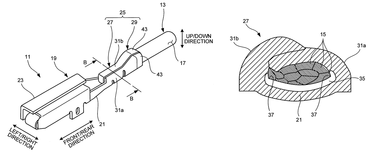
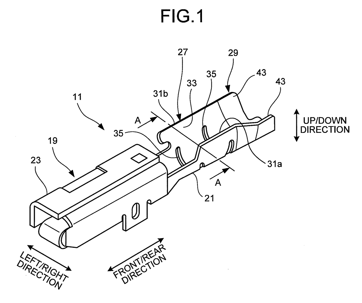
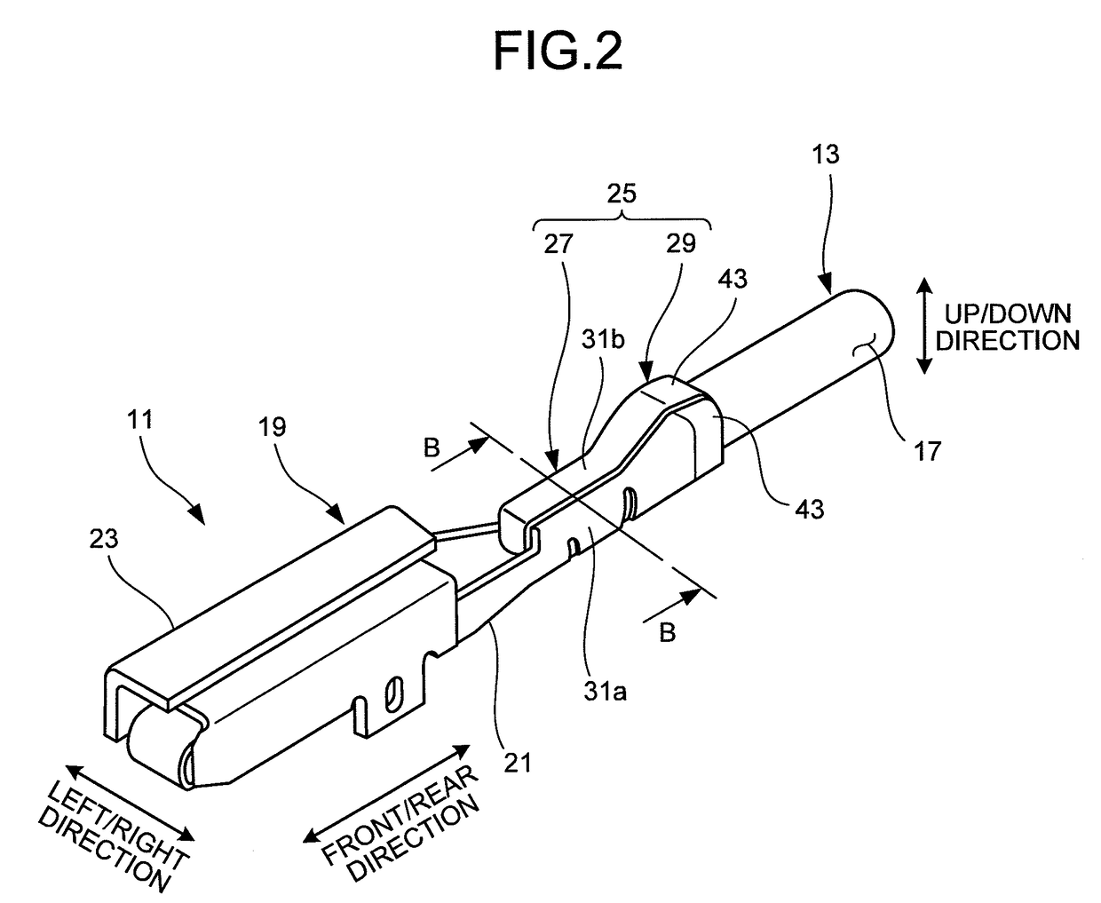
[0029]A crimping terminal 11 illustrated in FIGS. 1 and 2, according to an embodiment of the present invention, is connected to a distal end of an aluminum electric wire (electric wire) 13. The aluminum electric wire 13 is a conductor 15 (refer to FIG. 3B or others) made of a plurality of aluminum or aluminum alloy strands being twisted together, with the outer periphery of the conductor being covered with an insulating sheath 17. At an end portion of the aluminum electric wire 13, the insulating sheath 17 has been removed by a predetermined length, exposing the conductor 15. The crimping terminal 11 is to be crimp-connected to this end portion. Specific examples of preferable aluminum alloy include an alloy of aluminum and iron. When this type of alloy is adopted, it is possible to enhance extendibility and strength (tensile strength, in particular), compared with the conductor...


PUM


Abstract

A crimping terminal includes a conductor crimping portion having a U-shaped cross section. The conductor crimping portion includes a base plate portion and a pair of conductor caulking pieces. On an inner surface of the conductor crimping portion, a conductor is disposed, being exposed to a distal end of an aluminum electric wire. The pair of conductor caulking pieces, extending upwardly from both side edges in a longitudinal direction of the base plate portion, are bent inwardly so as to wrap the conductor of the aluminum electric wire to caulk the conductor such that the conductor is in close contact with the inner surface of the base plate portion. On the inner surface of the conductor crimping portion, a protruding indent is provided so as to extend continuously.

Description

CROSS-REFERENCE TO RELATED APPLICATION[0001]This application is a continuation application of International Application PCT / JP2014 / 056883, filed on Mar. 14, 2014, and designating the U.S., the entire contents of which are incorporated herein by reference.BACKGROUND OF THE INVENTION[0002]1. Field of the Invention[0003]The present invention relates to a crimping terminal.[0004]2. Description of the Related Art[0005]As a crimping terminal for an electrical equipment system of an automobile, for example, a crimping terminal of an open barrel type having a conductor crimping portion with substantially a U-shaped cross section has been used. Generally, for caulking this kind of crimping terminal, caulking referred to as B crimp is performed (refer to Japanese Patent Application Laid-open Nos. 2011-96451 and 2011-96452).[0006]As illustrated in FIG. 6, a crimping terminal 501 on which the B crimp is performed includes an electrical connecting portion 507 to be connected to a mating connecto...

Claims


Application Information

Patent Timeline
Patent Type & Authority Patents(United States)
IPC IPC(8): H01R4/18H01R4/62
CPCH01R4/18H01R4/185H01R4/188H01R4/62
Inventor SAKAGUCHI, TADAHISA
Owner YAZAKI CORP
Why Eureka
Try Eureka