Method and system for adjusting the alignment of a photonic beam

a technology of photonic beams and alignment devices, applied in the field of photonic beam alignment adjustment devices, can solve problems such as unsatisfactory alignment, and achieve the effect of eliminating the need for an operator

Inactive Publication Date: 2017-03-21
JEANOLOGIA
View PDF13 Cites 0 Cited by
  • Summary
  • Abstract
  • Description
  • Claims
  • Application Information

AI Technical Summary

Problems solved by technology

In most situations, this implies that the systems are not perfectly aligned, or that usually, extensive training and adjustment maneuvers are needed to optimally adjust the alignment.

Method used


Image

  • Method and system for adjusting the alignment of a photonic beam
  • Method and system for adjusting the alignment of a photonic beam
  • Method and system for adjusting the alignment of a photonic beam

Examples


Embodiment Construction

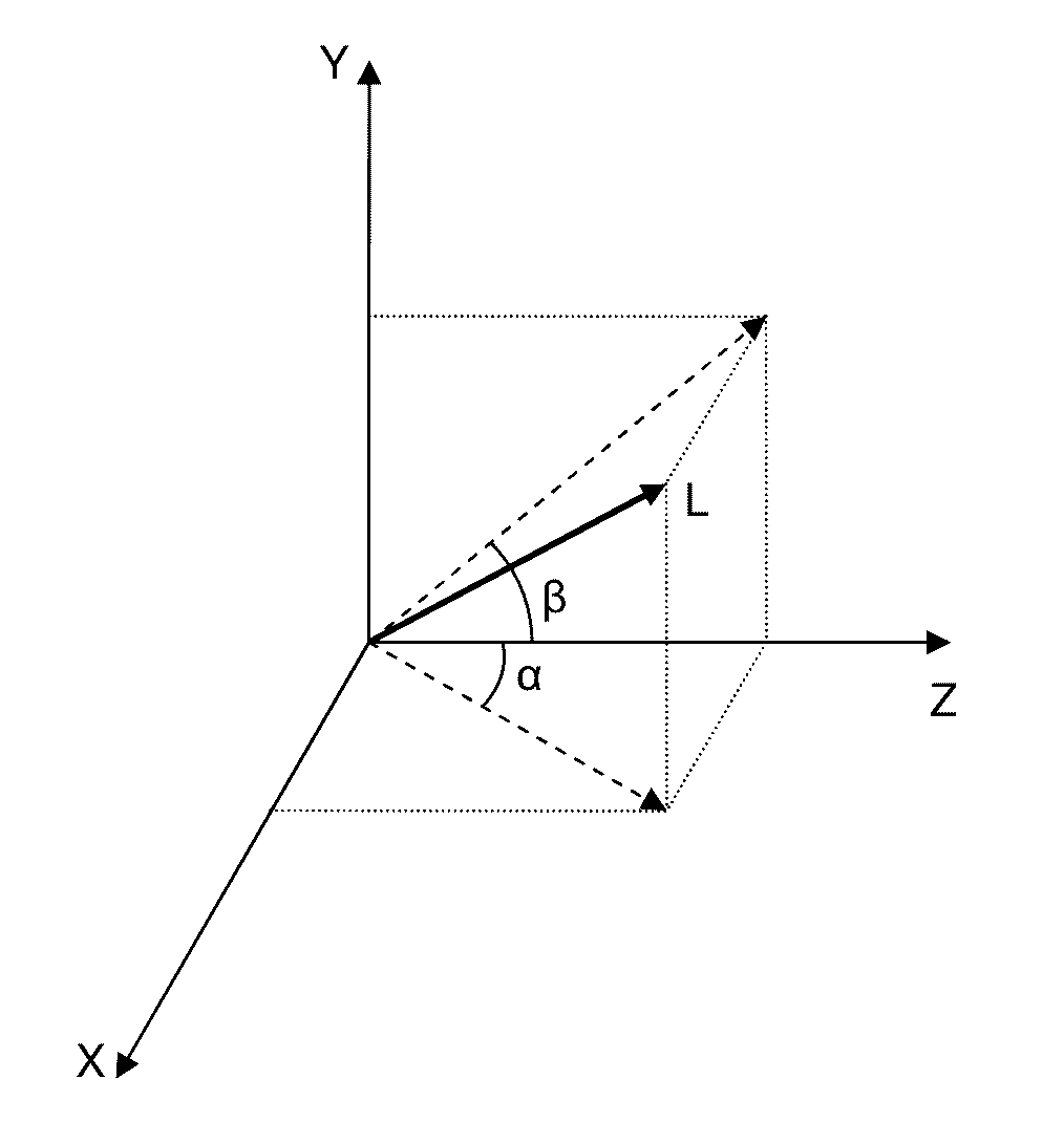
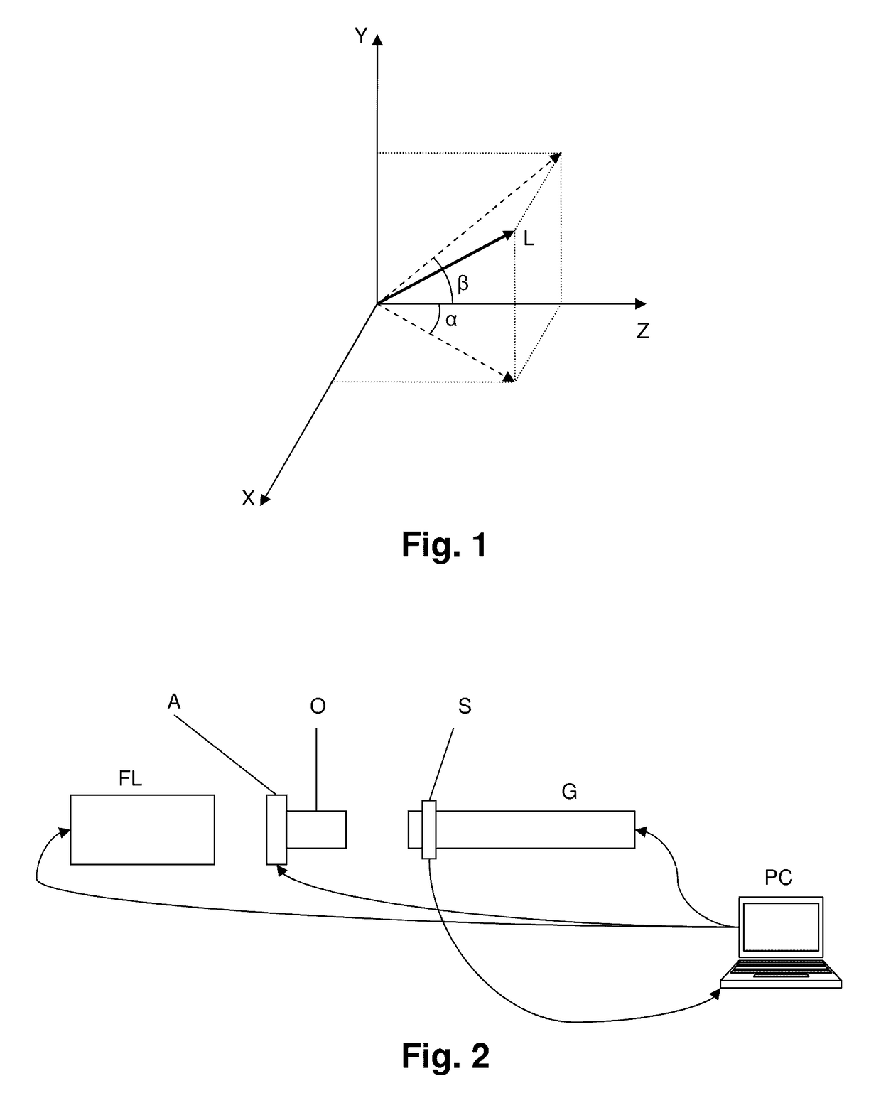
[0048]FIG. 2 illustrates the system proposed by the second aspect of the invention, together with a source of laser light FL, to create an exemplary embodiment in which the means of detection include a mobile sensor S, which moves up and down the optical axis Z, along the guide means G, between the positions which are occupied by the previously described first and second XY planes, in order to carry out positional detections in both XY planes.

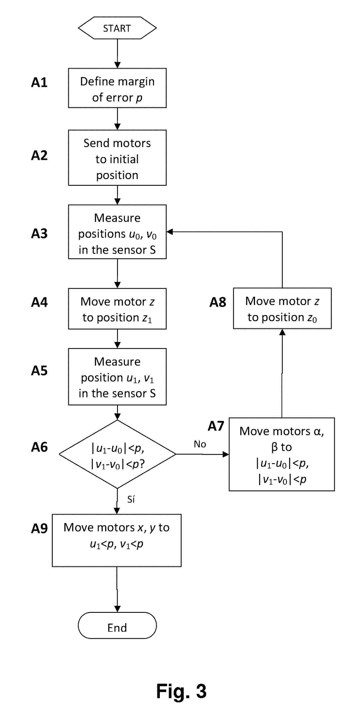
[0049]Said mobile sensor S is connected with the computational unit PC of the means of control, so that it is controlled by that unit, and it supplies it with the positional readings which it carries out, in order that this unit carry out the comparisons between those readings, and also adjust the angle according to the angle α and / or the angle β, as well as carry out positional adjustments according to the X coordinate axis and / or the Y coordinate axis of the photonic beam L, or consider the beam as correctly adjusted, if that is the case.

[005...


PUM

PropertyMeasurementUnit
trajectoryaaaaaaaaaa
degrees of freedomaaaaaaaaaa
angleaaaaaaaaaa

Abstract

The method comprises:detecting the positions (uo, vo) and (u1, v1) of said photonic beam (L) according to the coordinate axes X, Y on a first and second plane XY, which cut an optical axis X at a first and second point, respectively;comparing the results of said positional detections (uo, vo) and (u1, v1), and:if there are discrepancies which lie outside the margin of error (p), adjusting the angle of the photonic beam (L) according to the angle α and / or the angle β in order to overcome said discrepancies; orif there are no discrepancies which lie outside said margin of error (p), considering the angle of said photonic beam (L) as being properly adjusted.The system is adapted to implement the method set out by the invention.

Description

TECHNICAL FIELD[0001]The present invention generally concerns, in a first aspect, a method for adjusting the alignment of a photonic beam, and more specifically, a method comprising the detection of the position of the photonic beam in two XY planes spaced out along an optical axis Z, and, should there be discrepancies in the positions of the two detections, make an adjustment to the axis of the photonic beam[0002]A second aspect of the invention concerns a system for adjusting the alignment of a photonic beam adapted to implement the method of the first aspect.PRIOR ART[0003]For most equipment for laser marking, cutting, and soldering, or any optical system in general, it is necessary to adjust the outgoing laser beam or any photonic source with respect to a certain optical, electro-optical, or opto-mechanical system.[0004]The current solution is the use of subjective adjustments, whether by using localizing targets, thermal papers, or in general, any system that requires an operat...

Claims


Application Information

Patent Timeline
Patent Type & Authority Patents(United States)
IPC IPC(8): G01B11/00H01S3/101B23K26/04G01B11/27G01B11/14
CPCH01S3/101B23K26/043G01B11/14G01B11/272B23K26/04G01B11/27G01M11/00
Inventor DE ECHANIZ, SEBASTIAN R.IBANEZ BARON, JOSE M.SANS RAVELLAT, RAMON
Owner JEANOLOGIA
Why Eureka
Try Eureka