Modular parcel terminal and method for sending parcels

a module and terminal technology, applied in the direction of casings/cabinets/drawers, instruments, casings/cabinets/drawers, etc., can solve the problems of high rental cost, too large terminals and space consumption, and high management cost, so as to optimize the usable space and manage high costs

Active Publication Date: 2017-03-28
CLEVERON LTD
View PDF14 Cites 28 Cited by
  • Summary
  • Abstract
  • Description
  • Claims
  • Application Information

AI Technical Summary

Benefits of technology

[0010]The aim of the present invention is to offer a solution of a modular parcel terminal that would be free from the previously mentioned drawbacks, safe, simple, fast, reliable, capacious and taking up little floor space that would enable accommodating as many parcels, postal packages, storable items, etc. as possible into one parcel terminal.
[0013]Due to the construction of the compartments, the solution according to the present invention allows, differently from the solutions known thus far, more comfortable and safer use by shorter people and people in wheelchairs.
[0014]The users can, differently from the solutions known so far, retrieve smaller parcels from the parcel terminal and enter their parcels much more easily and conveniently thanks to the moving compartments. In order to retrieve or enter the package, the moving compartment automatically opens forward and since the moving compartment is open-topped, independent of the position of the parcel in the compartment, it is comfortable for the user to take it out, or to enter it into the compartment because it is not necessary to push hand inside the compartment; whereas the position of the parcel in the compartment is well visible for the user.
[0015]Thanks to the moving compartments it is possible to make significantly narrower modules, compared to the width of the doors of the compartments known from the level of technology, where compartments are meant for smaller parcels.
[0019]As statistics claim that only ⅙ of the whole space of the smallest compartment is used purposefully, then an additional aim of the present invention is to optimize the usable space and the compartments with doors have been replaced with open-topped moving compartments that accommodate smaller parcels, for example, letters, smaller books, pens, essentials, cosmetic products or other items that take up very little space in the widely known solutions featuring compartments with doors thus making the managing costs high because most of the space in the parcel terminal remains unused.
[0020]The solution according to the present invention also enables, in different embodiments, the usage of narrower compartments for small parcels compared to what has so far been used in the thus far known solutions of locker compartments with doors.

Problems solved by technology

In the case of different senders and recipients it is preferred to use separate lockers for each parcel, which is why the terminals are too big and space-consuming in order to accommodate enough parcels.
For example, it is expensive to use the services of parcel terminals in the shopping and entertainment centers, sports centers, airports, etc. where there is little floor space and the rental space is expensive.
However, the parcel terminals cannot, at the same time, be built higher because shorter people or people in wheelchairs would not be able to retrieve postal objects from higher lockers, or place packages there.
Similarly, in the case of smaller packages, it is complicated for users to get them from lower or higher lockers.
Although there are lockers of smaller height for storing or sending smaller parcels, however, they are inconvenient to use because due to the depth of the space, the parcel may, upon sending, move to the back wall and therefore it is complicated to retrieve that parcel.
Widely known parcel terminals are thus of smaller storage capacity, take up too much space, are inconvenient for the user while entering small-sized packages, letters and other items for storage or sending, and upon retrieving.
The generally known solutions have used doors, which is why it is complicated to retrieve items when they have been placed further inside the locker space.
It is also complicated to retrieve or take out smaller items from higher lockers.
The drawback of such a solution is that most of the space in the terminal or drawer, in the case of smaller packages or stored items, has been left unused.
As it is statistically known that people tend to send smaller packages more often, then in such an automated terminal, with the lockers empty for the most part, most of the automated terminal space is unused which makes the cost per terminal very big; or, when it is a location with lots of users, more terminals must be added which, in its turn increases the cost.
Another drawback of such a solution is its uncomfortable usage since the courier, the recipient or sender of the package and also the person storing items has problems retrieving parcels from the highest or lowest lockers because it is not clearly visible where the parcel is located and / or it is hard to reach the parcel, or it is necessary to stretch hands deep into the locker.
In addition to the known solutions there is also a problem with the situation of receiving bigger parcels where the measures of the cross sections of the parcel are approximately the same as the measures of the locker and the parcel has tightly been pushed into the locker.
By trying to get their fingers between the parcel and the locker walls, the users may injure themselves or damage the parcel.
Furthermore, the solution described in the patent application GB2437967, or other known solutions depending on the location of the parcel terminal, season and the habits of the users does not enable the possibility to offer users more versatile usage options with terminals with a suitable size and number of lockers.

Method used


Image

  • Modular parcel terminal and method for sending parcels
  • Modular parcel terminal and method for sending parcels
  • Modular parcel terminal and method for sending parcels

Examples


Embodiment Construction

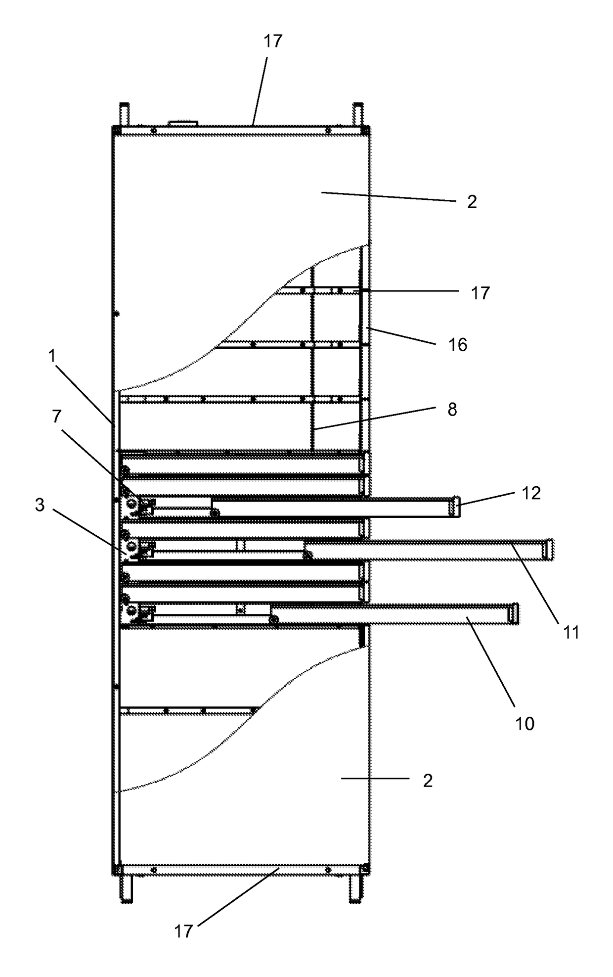
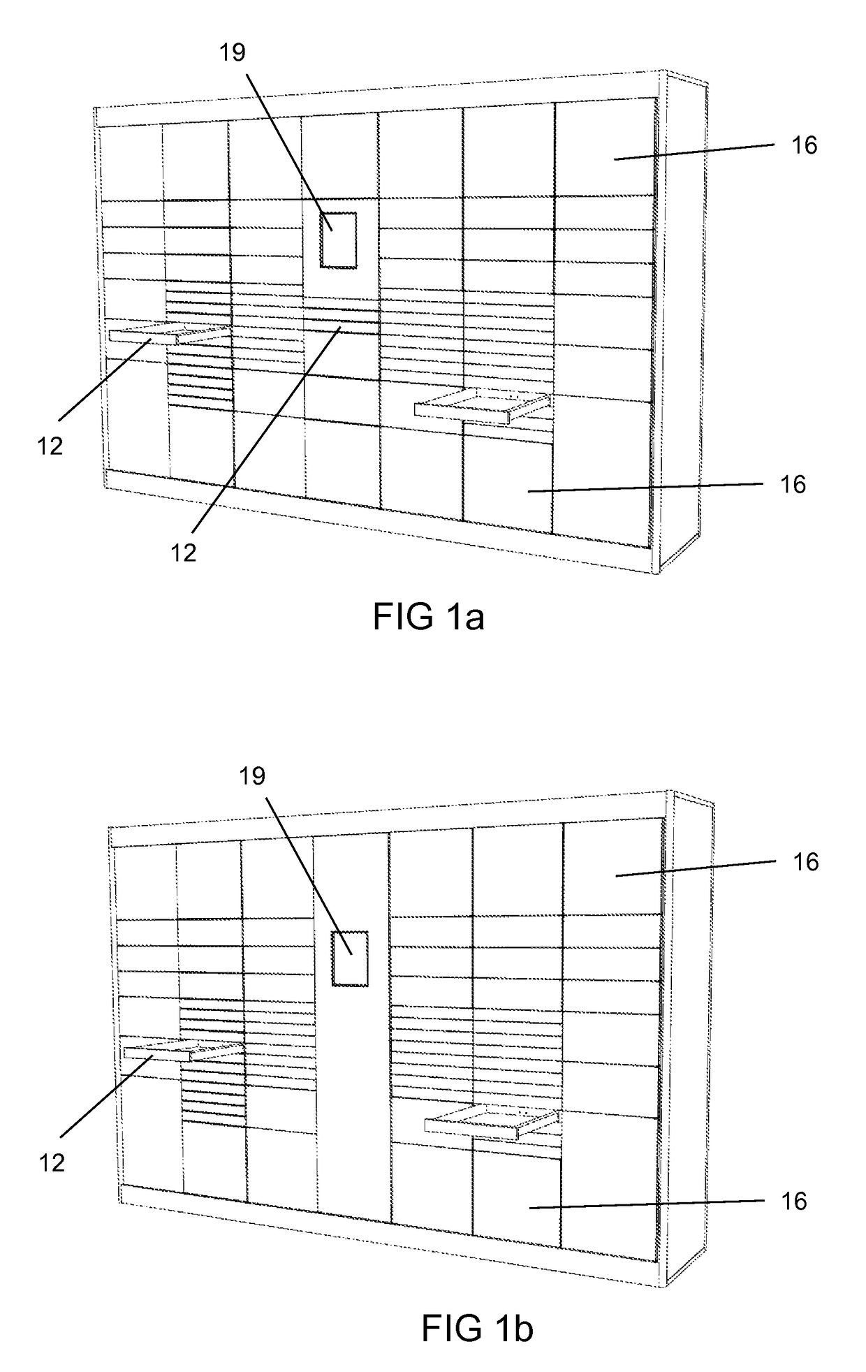
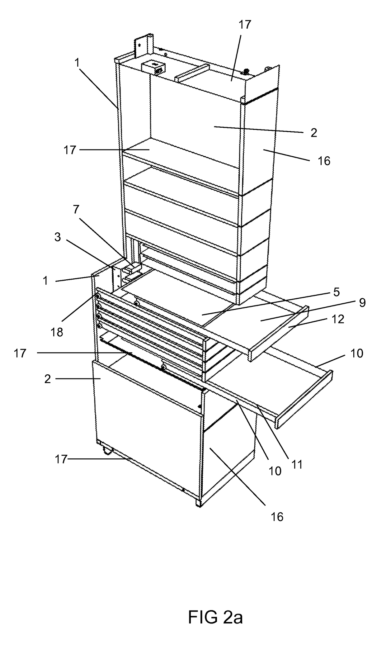
[0033]The modular parcel terminal according to the present invention has been built from modules comprising outward moving open-topped compartments and compartments with doors 16 and a console module that comprises the electronics system 19.

[0034]The module of the modular parcel terminal according to the present invention comprises a rear panel 1, side walls 2, cable conduit 3, sections comprising compartments with doors 16 and moving compartments and comprises wires / cables, locking devices and hinges for doors 16, support wheels for rails 4, locking and moving mechanism 7 for moving compartments, locking system 8 preventing pulling out the compartment and electronics system 19 comprising cables, a computer, printer, camera, touchpad, screen or touch screen, scanner and / or other electronic devices for identifying the user, making payments and / or placing orders.

[0035]The outward moving compartment comprises a bottom 9, the edges of which have been bent into sides 10 and the edges of ...


PUM


Abstract

The modular parcel terminal according to the present invention has been built from modules comprising outward moving open-topped compartments and compartments with doors and the console module. The outward moving open-topped compartments have been located in the parcel terminal in such a pattern that would allow achieving the maximum capacity of the parcel terminal and that it would be comfortable and safe for the user to enter and retrieve parcels, postal packages, storable items at the parcel terminal. The modules of the parcel terminal have been built in such a way that allows them to be connected with each other according to the need of storage space in a particular parcel terminal exploitation area.

Description

PRIORITY[0001]This application claims priority of European application EP14170713 filed on May 30, 2014 and of European application EP 1477916 filed on Jul. 7, 2014, and the contents of both of which are fully incorporated herein by reference.FIELD OF THE INVENTION[0002]The present invention relates to the field of self-service parcel terminals, more specifically to the field of delivery, sending and receiving parcels, packages, mail and other postal objects.BACKGROUND OF THE INVENTION[0003]From the level of technology it is known of several different automated parcel sending devices and terminals. Widely known are the package or parcel terminals that have a locker with a separate door for each postal object or storage item. Such widely known solutions have several drawbacks.[0004]The generally known parcel terminal solutions are of the kind where they have been placed in a long row alongside a wall, with their backs against each other or they have been built from modules that allow...

Claims


Application Information

Patent Timeline
Patent Type & Authority Patents(United States)
IPC IPC(8): B07C7/02H05K5/02A47F10/02G07F17/12A47G29/14
CPCB07C7/02A47F10/02G07F17/12H05K5/0221A47G2029/145A47G2029/149A47G29/141
Inventor LOSSOV, REMIHIRVESAAR, LAURIPETTAI, INDREK
Owner CLEVERON LTD
Why Eureka
Try Eureka