Area vacuum gripper

a vacuum gripper and surface area technology, applied in the direction of gripping heads, manipulators, manufacturing tools, etc., can solve the problems of occupying space for externally placed control valves, affecting the operation of vacuum generators, so as to achieve the effect of convenient retrofitting

Active Publication Date: 2017-03-28
J SCHMALZ GMBH
View PDF11 Cites 1 Cited by
  • Summary
  • Abstract
  • Description
  • Claims
  • Application Information

AI Technical Summary

Benefits of technology

[0006]The present invention overcomes the disadvantages of the related art in a reliably operable surface area vacuum gripper, which can be easily retrofitted for operation with other vacuum generators or for other functions.

Problems solved by technology

Surface area vacuum grippers of this type are relatively difficult to retrofit to other vacuum generators.
Furthermore, externally placed control valves take up space and are exposed to the risk of damage.

Method used


Image

  • Area vacuum gripper
  • Area vacuum gripper

Examples


Embodiment Construction

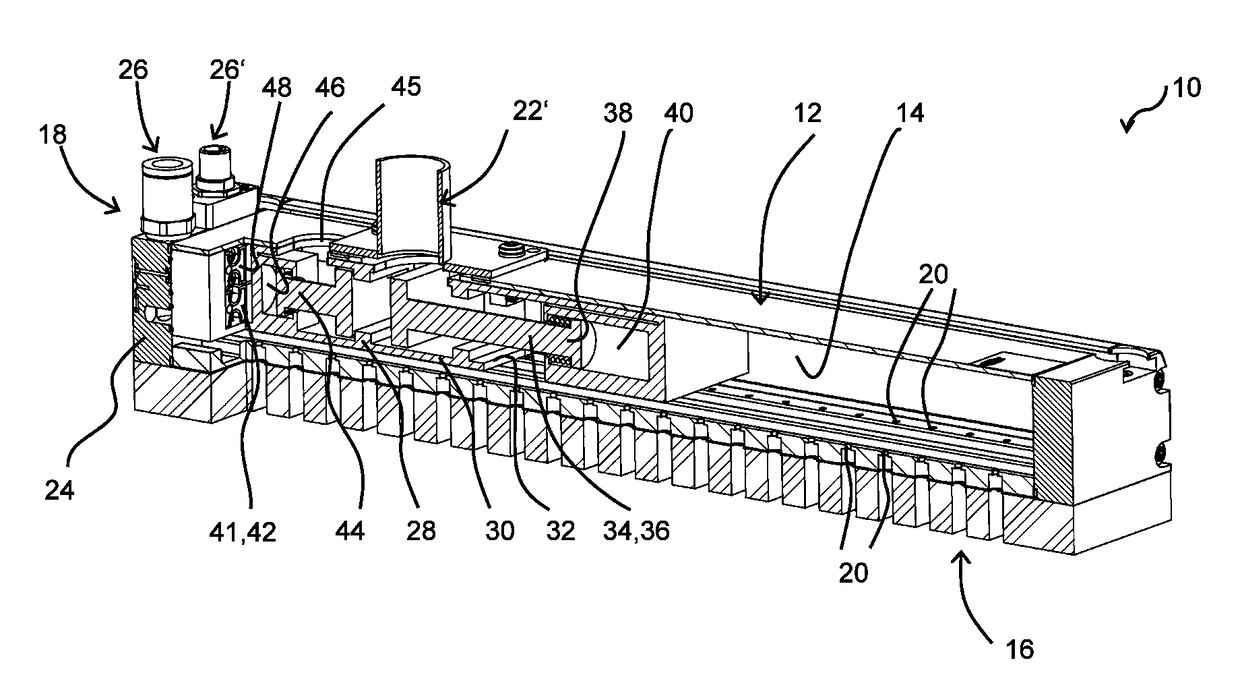
[0017]The surface area vacuum gripper of the present invention is generally indicated at 10 in the figures, where like reference numerals are used to identify like structure throughout the drawings. The surface area vacuum gripper 10 has a substantially box-shaped housing 12 in the depicted example, which is depicted in FIG. 1 in a longitudinal section. The housing 12 delimits a suction chamber 14 in its interior, and has a suction side 16, to which a workpiece, not shown, can be applied and suctioned onto when the surface area vacuum gripper is in operation. The housing 12 has an end surface 18 differing from the suction side 16, formed by a narrow side of the box-shaped housing 12 in the depicted example. The housing 12 has numerous suction openings 20, which pass through the suction side 16 in the depicted example, and thus form a flow connection to the suction chamber 14.

[0018]The surface area vacuum gripper 10 depicted in FIG. 1 is designed to be operated with an external vacuu...


PUM


Abstract

A surface area vacuum gripper having a housing with suction openings for sucking a workpiece to be gripped, at least one cover plate that seals the end face of the housing, an insertion element that can be inserted into the housing, wherein the insertion element can be fixed at the cover plate and comprises at least one opening which is flow-connected with the suction openings in the housing, the cover plate comprising a compressed air inlet. The insertion element comprises a functional device for controlling a flow through the opening of the insert.

Description

CROSS-REFERENCE TO RELATED APPLICATIONS[0001]The present application is a National Stage of International Patent Application No. PCT / EP2014 / 051028, filed on Jan. 20, 2014, which claims priority to and all the benefits of German Patent Application No. 10 2013 201 250.0, filed on Jan. 25, 2013, both of which are hereby expressly incorporated herein by reference in their entirety.BACKGROUND OF THE INVENTION[0002]1. Field of the Invention[0003]The invention relates to a surface area vacuum gripper having a housing, at least one cover plate that seals the end surface of the housing, an insert element that can be inserted into the housing, wherein the insert element can be attached to the cover plate and has at least one opening that has a flow connection to suction openings in the housing, and the cover plate has a pressurized air inlet, to which a pressurized air supply can be connected.[0004]2. Description of the Related Art[0005]Surface area vacuum grippers are constructed in the know...

Claims


Application Information

Patent Timeline
Patent Type & Authority Patents(United States)
IPC IPC(8): B25J15/06B65G47/91
CPCB25J15/0616B25J15/0625B65G47/91
Inventor HARTER, LEONHARD
Owner J SCHMALZ GMBH
Why Eureka
Try Eureka