Rear vehicle-body structure of vehicle

a vehicle and rear body technology, applied in the direction of superstructure subunits, resilient suspensions, suspensions, etc., can solve the problems of inward falling down, inability to properly perform load-transmission functions, and long distance between damper and pillar portion, so as to reduce the weight of the vehicle body and prevent the inward falling down

Active Publication Date: 2017-03-28
MAZDA MOTOR CORP
View PDF14 Cites 6 Cited by
  • Summary
  • Abstract
  • Description
  • Claims
  • Application Information

AI Technical Summary

Benefits of technology

[0006]An object of the present invention is to provide a rear vehicle-body structure of a vehicle which can achieve both reduction of a vehicle-body weight and prevention of the inward falling-down regardless of the length of the wheel base.
[0008]According to the rear vehicle-body structure of the vehicle of the present invention, since the pillar-reinforcement ridge portion and the reinforcing-member ridge portion are arranged to align substantially straightly regardless of a longitudinal positional relationship of the rear wheel house and the pillar portion, the damper load inputting to the reinforcing member can be efficiently transmitted to a front side portion of the pillar portion which is spaced apart from the rear wheel house, restraining its dispersion to the side panel inner located near the rear wheel house, so that the damper load's dispersion can be properly dispersed to a vehicle-body reinforcing member, such as the roof rail, via an entire part of the pillar portion. Thereby, the inward falling-down of the side panel inner which is caused by the damper load can be properly prevented, without increasing the plate thickness of steel plates or adding other reinforcing members.
[0009]In an embodiment of the present invention, the pillar reinforcement comprises a front-side flange portion which is configured to have a crank-shaped horizontal cross section and joined to the side panel inner, a body portion which connects to the front-side flange portion via a front-side ridge portion extending vertically, and a rear-side flange portion which connects to the body portion via the pillar-reinforcement ridge portion and is joined to the reinforcing member. According to this embodiment, the connectional rigidity of the pillar reinforcement and the reinforcing member can be increased, increasing the rigidity of the pillar portion, so that the transmission efficiency of the damper load to the front side portion of the pillar portion can be increased.
[0010]In another embodiment of the present invention, the rear wheel house has a slant face portion which is configured such that a front side thereof is positioned relatively downward compared to a rear side thereof at a top portion thereof, the reinforcing member has a front-end flange portion which extends forward from a lower end of a front wall portion thereof and is joined to the slant face portion of the rear wheel house, and a cross angle of the front wall portion and the front-end flange portion of the reinforcing member is set at substantially 90 degrees. According to this embodiment, a space for welding work between the reinforcing member and the top portion of the rear wheel house can be ensured, so that the connectional rigidity by the welding of the reinforcing member and the top portion of the rear wheel house can be increased.
[0011]In another embodiment of the present invention, the rear vehicle-body structure further comprises a suspension housing which connects to the rear wheel house in back of the pillar reinforcement and supports a damper of a suspension, wherein a cross portion of an extension line of the pillar-reinforcement ridge portion and the reinforcing-member ridge portion and the top portion of the rear wheel house is located substantially at the same longitudinal position as a cross portion of an extension line of an axial center of the damper and the top portion of the rear wheel house when viewed from the side. According to this embodiment, the length of a load-transmission path from the damper to the front side portion of the pillar portion can be minimized, so that the transmission efficiency of the damper load can be further increased.

Problems solved by technology

Accordingly, an inward-component of a damper load acting on the suspension housing in a vertical direction acts on a vehicle body, so that there is a problem in that the above-described inward-component of the damper load may cause the side panel inner located near the suspension housing to fall down inward, i.e., there may occur a so-called inward falling-down problem.
However, in a case in which a wheel base is designed to be long from a vehicle-design requirement, a distance between the damper and the pillar portion becomes so long that it becomes difficult to perform the load-transmission function properly.

Method used


Image

  • Rear vehicle-body structure of vehicle
  • Rear vehicle-body structure of vehicle
  • Rear vehicle-body structure of vehicle

Examples


Embodiment Construction

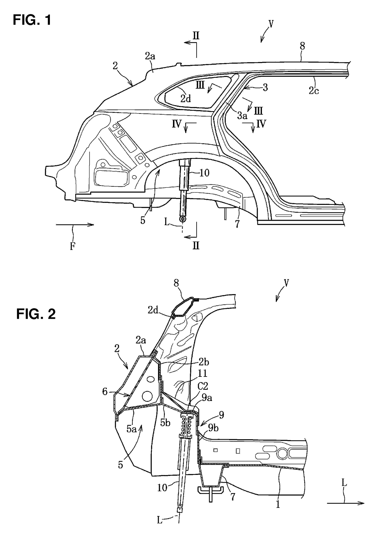
[0023]Hereafter, embodiments of the present invention will be described. In the embodiments described, an arrow F shows a forward direction and an arrow L shows a left direction.

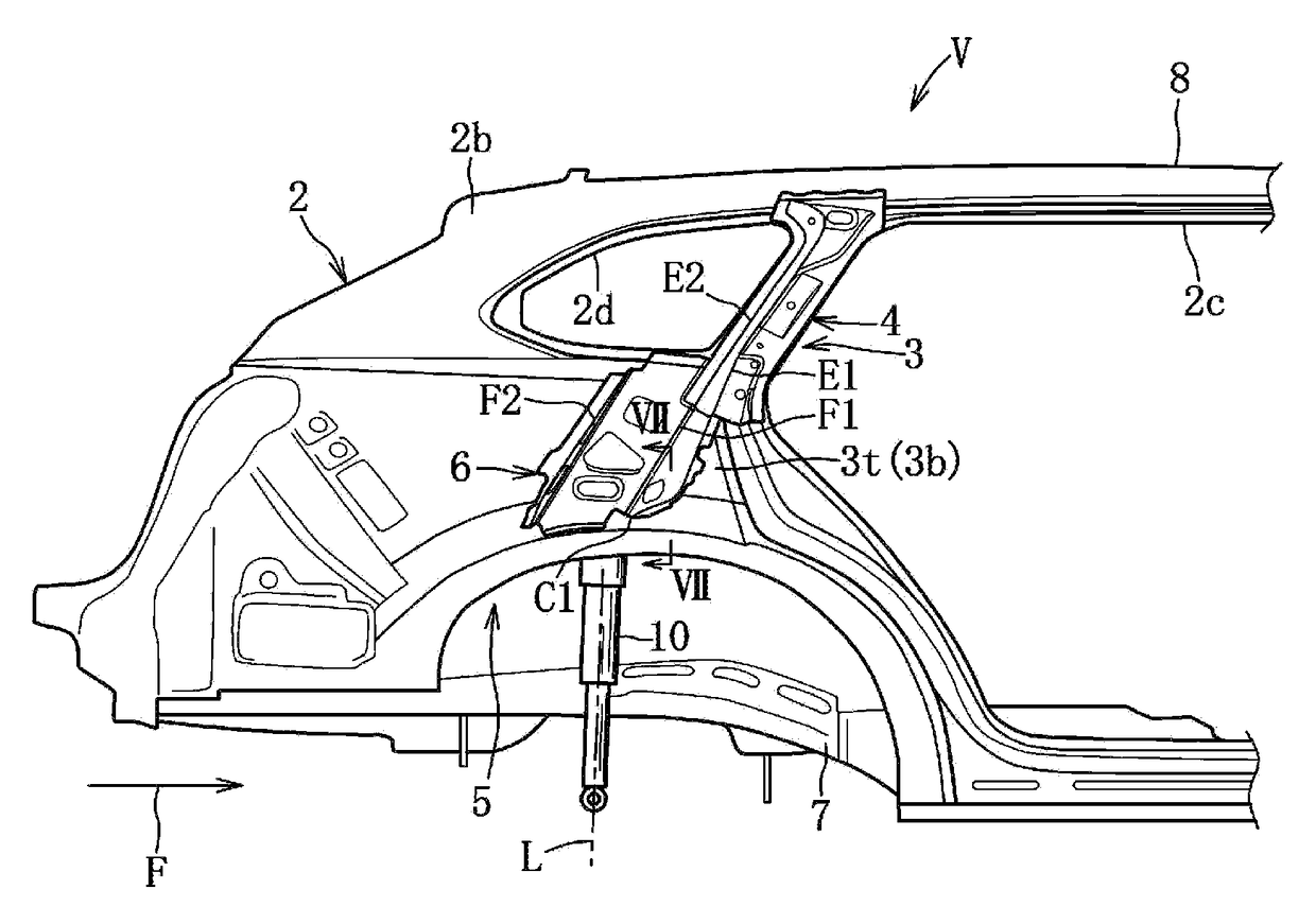
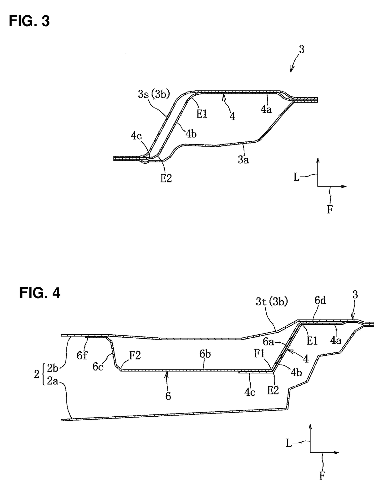
[0024]A first embodiment of the present invention will be described referring to FIGS. 1-9. As shown in FIGS. 1 and 5, a vehicle V of the present embodiment is a 4-door type of hatch-back vehicle which is provided with a lift gate (not illustrated) at a rear-side portion. The vehicle V comprises a floor panel 1, a pair of right-and-left side panels 2, a pair of right-and-left rear pillars 3, a pair of right-and-left rear pillar reinforcements 4, a pair of right-and-left rear wheel houses 5, a pair of right-and-left outside reinforcing members 6 (reinforcing members), a pair of right-and-left rear suspensions (not illustrated), and others.

[0025]The floor panel 1 will be described first. As shown in FIG. 2, the floor panel 1 is provided in a vehicle width direction between the pair of rear side frames 7, exten...


PUM


Abstract

A rear pillar inner provided at a side panel inner and extending upward from a front-side upper portion of a rear wheel house, a rear pillar reinforcement joined to an outside portion of the rear pillar inner, and an outside reinforcing member connecting an outside portion of the side panel inner and the rear wheel house are provided. The rear pillar reinforcement has a rear-side pillar-reinforcement ridge portion extending vertically. The outside reinforcing member has a front-side reinforcing-member ridge portion extending vertically. A lower end portion of the rear pillar reinforcement and an upper end portion of the outside reinforcing member are joined such that the both ridge portions are arranged to align substantially straightly, when viewed from the side, and to slant in such a manner that an upper side thereof is positioned relatively forward compared to a lower side thereof.

Description

BACKGROUND OF THE INVENTION[0001]The present invention relates to a rear vehicle-body structure of a vehicle, and in particular, relates to the rear vehicle-body structure of the vehicle comprising a pillar reinforcement and a reinforcing member connecting an outside portion, in the width direction of the vehicle, of a side panel inner and a rear wheel house.[0002]Conventionally, a suspension of the vehicle is provided with a damper to damp (suppress) vibrations and impacts during the vehicle's traveling for ensuring the maneuverability and stability of the vehicle operated by a driver. This damper is arranged to slant such that an upper side therefore is positioned relatively inward compared to a lower side thereof, and its upper end is supported at a suspension housing (suspension tower) which is formed above the wheel house. Accordingly, an inward-component of a damper load acting on the suspension housing in a vertical direction acts on a vehicle body, so that there is a problem...

Claims


Application Information

Patent Timeline
Patent Type & Authority Patents(United States)
IPC IPC(8): B62D25/04B62D25/08B60G3/01B62D25/16
CPCB62D25/04B60G3/01B62D25/087B62D25/088B62D25/16
Inventor FUJII, HIROAKIMURAOKA, SHUJIIKEDA, TOSHIHARU
Owner MAZDA MOTOR CORP
Why Eureka
Try Eureka