
Reel frame for fishing

a reel frame and fishing technology, applied in the field of reel frames for fishing, can solve the problems of increased production costs, increased production costs, and increased production costs, and achieve the effects of improving the machinability of preset inventions, facilitating the holding of reel frames, and maximizing the portion chamfering by lathe processing

Active Publication Date: 2017-04-04
DOYO ENG
View PDF14 Cites 4 Cited by
  • Summary
  • Abstract
  • Description
  • Claims
  • Application Information

AI Technical Summary

Benefits of technology

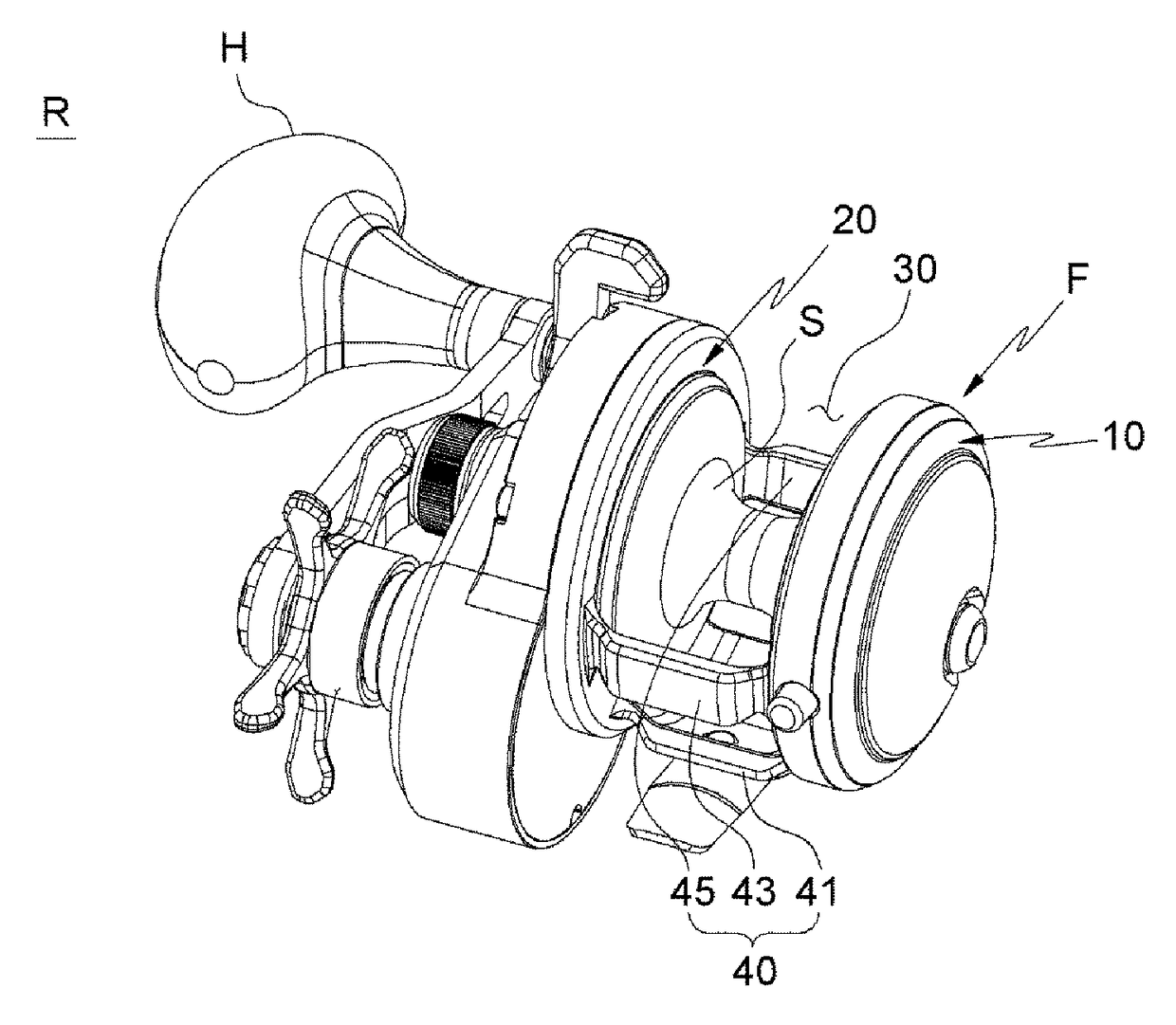
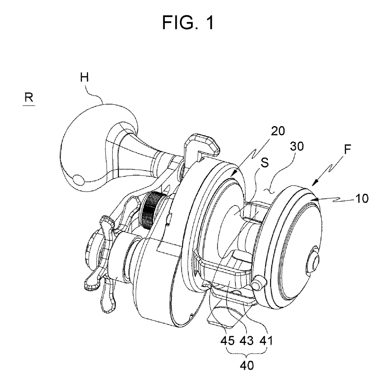
[0010]Accordingly, the present invention has been made keeping in mind the above problems occurring in the related art, and the present invention is intended to propose a reel frame for fishing that has improved machinability and productivity with a minimized machining cost by reducing the portions, which requires milling which rotates and feeds a cutting tool and needs a relatively high cost, but by maximizing the portions, which requires lathe processing which rotates a workpiece, feeds a cutting tool, and needs a relatively low cost, that can be rounded at the portions, which user's hands or body comes in contact with, through chamfering, particularly, inside chamfering.
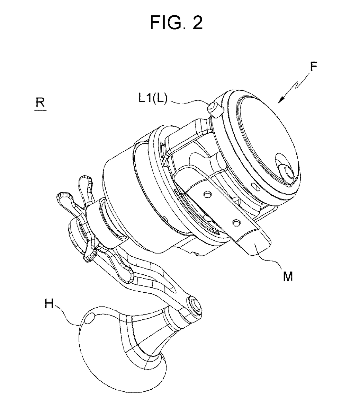
[0011]Another object of the present invention is to provide a reel frame for fishing in which, when a connecting unit for maintaining a spool space between a palm-facing first panel and a gear-facing second panel includes first rib for coupling a fishing rod mount and a second or a third rib for reinforcement, the portions that a human body comes in contact with are rounded by lathe processing that rotates a metal ingot such as aluminum and feeds a cutting tool, in which the first to third ribs are configured to have a body and curved ends for coupling the first and second panel at both ends of the body in order to perform lathe processing for making machined corners of the first and second panels, which are the main portions to be machined in lathe processing, that is, inside chamfered portions, which are difficult to make relative to outside chamfered portions and brought in contact with the space; recesses are formed between the curved ends and the first and second panels, and a cutting tool rotated for lathe processing can approach the inside chamfered portions of the first and second panels of the metal ingot due to the recesses, so the portions chamfered by lathe processing are maximized.
[0012]Another object of the present invention is to provide a reel frame for fishing that allows a user to easily hold a reel frame and do various types of work by making a first panel smaller in area than a second panel when being seen from a side.
[0015]According to the reel frame for fishing that has improved machinability of the preset invention, when a connecting unit for maintaining a spool space between a palm-facing first panel and a gear-facing second panel includes first rib for coupling a fishing rod mount and a second or a third rib for reinforcement, the portions that a human body comes in contact with are rounded by lathe processing that rotates a metal ingot such as aluminum and feeds a cutting tool, in which the first to third ribs are configured to have a body and curved ends for coupling the first and second panel at both ends of the body in order to perform lathe processing for making machined corners of the first and second panels, which are the main portions to be machined in lathe processing, that is, inside chamfered portions, which are difficult to make relative to outside chamfered portions and brought in contact with the space; recesses are formed between the curved ends and the first and second panels, and a cutting tool rotated for lathe processing can approach the inside chamfered portions of the first and second panels of the metal ingot due to the recesses, so the portions chamfered by lathe processing are maximized. Further, a user can easily hold a reel frame and do various types of work by making a first panel smaller in area than a second panel when being seen from a side. Accordingly, by reducing the portions, which requires milling which rotates and feeds a cutting tool and needs a relatively high cost, but by maximizing the portions, which requires lathe processing which rotates a workpiece, feeds a cutting tool, and needs a relatively low cost, it is possible to round the portions, which user's hands or body comes in contact with, through chamfering, particularly, inside chamfering.

Problems solved by technology

However, these technologies are all not in associated with cutting characteristics of fishing reel frames.

Method used


Image

  • Reel frame for fishing
  • Reel frame for fishing
  • Reel frame for fishing

Examples


Embodiment Construction

[0019]The present invention will be described hereafter in detail with reference to the accompanying drawings.

[0020]The present invention may be modified in various ways and implemented by various exemplary embodiments, so that aspects (or exemplary embodiments) are shown in the drawings and will be described in detail. However, it is to be understood that the present invention is not limited to the specific exemplary embodiments, but includes all modifications, equivalents, and substitutions included in the spirit and the scope of the present invention.

[0021]Reference numerals in the drawings, particularly, reference numerals that are the same in tens and units, or tens, units, and letters indicate the components having the same or similar functions, and if not specifically stated, the components indicated by those reference numerals can be considered as components following this standard.

[0022]Components in the drawings may be shown excessively large (or thick) or small (or thin) ...


PUM


Abstract

Provided is a reel frame for fishing that has improved machinability and productivity with a minimized machining cost by reducing the portions that requires milling, but by maximizing the portions that requires lathe processing. The reel frame for fishing includes: a palm-facing first panel; a gear-facing second panel; a spool space between the first and second panel; and a connecting unit maintaining the space and including a first rib connecting the first and second panel to each other and combined with a fishing rod mount, in which the first rib has a body and curved ends at both sides of the body to make a recess between the first and second panels and the first rib, for lathe processing for making inside chamfered portions around inner sides of the first and second panels.

Description

BACKGROUND OF THE INVENTION[0001]Field of the Invention[0002]The present invention relates to a reel frame for fishing that can be more efficiently machined. In detail, the present invention relates to a reel frame for fishing that has improved machinability and productivity with a minimized machining cost by reducing the portions, which requires milling which rotates and feeds a cutting tool and needs a relatively high cost, but by maximizing the portions, which requires lathe processing which rotates a workpiece, feeds a cutting tool, and needs a relatively low cost, that can be gripped well and stably held in a hand by rounding the portions, which user's hands or body comes in contact with, through chamfering, particularly, inside chamfering.[0003]Description of the Related Art[0004]Plastic molds and die casting frames are used for reels such as bait reels for hooking relatively small fishes, but high-strength frames manufactured by cutting a metal ingot (bar-shaped ingot) such a...

Claims


Application Information

Patent Timeline
Patent Type & Authority Patents(United States)
IPC IPC(8): A01K89/01A01K89/015A01K89/0165
CPCA01K89/0192A01K89/0165
Inventor HYUN, KWANG HO
Owner DOYO ENG
Learn More