Screening panel and method of fixing

a technology of fixing and screen, applied in the direction of screening, chemistry apparatus and processes, solid separation, etc., can solve the problems of screen surface disconnection or release from the frame, screen panel wear, and significant vibration of the panel assembly, so as to reduce the available flex of the screen, reduce the flex, and reduce the effect of pulling

Active Publication Date: 2017-04-04
LETTELA PTY LTD
View PDF13 Cites 21 Cited by
  • Summary
  • Abstract
  • Description
  • Claims
  • Application Information

AI Technical Summary

Benefits of technology

[0016]A problem with some prior art screen panels is that over time, material being screened can become stuck within openings of the screen surface to block those openings and if sufficient openings become blocked, the screen surface becomes clogged and is no longer capable of proper screening. In that case, the vibratory machinery must be shut down to clear the openings of the screen surface. Blockage of openings is reduced or less likely where the screen surface can oscillate between the sides and ends of the frame during a screening operation. Such oscillation can clear the openings of blockage while the vibratory machinery is operating and thus remove the need for shutdown. Prior art screen panels in which the frame is encapsulated with the screen often provide only a small amount of potential oscillation, because the frame normally has a central stiffening member that is encapsulated and so the free distance for oscillation is from the central member to the side and end members. However, in the present invention the screen is separate from the frame, ie the frame is not encapsulated within the screen, and even where a central stiffening member is provided, the screen surface can still oscillate relative to that member, so that the free distance for oscillation is fully across the screen surface between the side and end members. This allows for increased oscillation and thus improved clearance of blocked openings. This is particularly advantageous in relation to high moisture ore clay type ores.
[0036]The arrangement of the invention discussed above is further advantageous in that the channel arrangement can be configured so that the flexibility of screen surface is maintained despite that the centre member (where provided) is captured within a channel. That configuration can be that the centre member is captured within a channel in a manner that the channel can shift relative to the centre member as the screen oscillates relative to the frame. Thus the channel can move upwardly and downwardly relative to the centre member as the screen oscillates but the centre member remains captured within the channel and fines or coarse ore are precluded or at least obstructed from entry into the channel. The side walls of the channel are thus configured to be a close and touching fit against the sides of the centre member, but that fit does not stop relative movement between the screen and the centre member.

Problems solved by technology

In the panel assembly described above, care must be taken in the design of the frame and screen surface, in particular in relation to the connection between them, given that in use, with the panel assembly applied to the deck of vibratory machinery, the panel assembly will be subject to significant vibration and the screen surface can disconnect or release from the frame if the connection between them is not sufficiently secure.
In all forms of screening apparatus, the material being screened (ores for example) causes the screen panels to wear over time, due to the abrasiveness of the ores or materials typically being screened, and thus the screen panels require periodic replacement.
Replacement causes downtime of the vibratory machinery and loss of output of the mine.

Method used


Image

  • Screening panel and method of fixing
  • Screening panel and method of fixing
  • Screening panel and method of fixing

Examples


Embodiment Construction

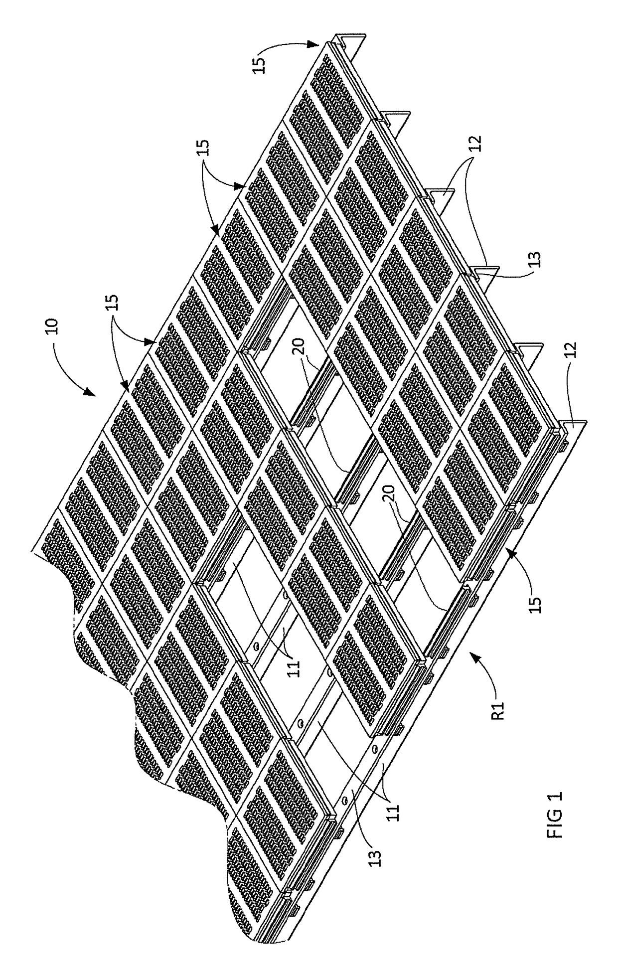
[0047]With reference to FIG. 1, a portion of a screening deck and subframe 10 of a vibratory machine is illustrated, comprising a plurality of elongate, longitudinal beams 11 each of which is formed from an angle of steel having a vertical portion 12 and a horizontal portion 13 disposed substantially at right angles. While the beams 11 extend in the longitudinal direction of the vibratory machine, the beams can equally extend perpendicularly to the longitudinal direction of the vibratory machine and the invention applies to that form of vibratory machine as well. The beams 11 can be of any length, such as increasing from 4′ to 28′ in 2′ increments. The width dimensions likewise can be of any length, such as increasing from 2′ to 14′ in 2′ increments.

[0048]The deck and subframe 10 illustrated in FIG. 1 is a portion of a vibratory machine only and does not show the side edge beams that define the edge of the screening deck. The portion of the deck and subframe that is shown in FIG. 1 ...


PUM


Abstract

A screen panel 15 for mounting to a vibratory screening apparatus that includes a plurality of beams 11 to which screen panels 15 can be mounted. The screen panel 15 comprises a square or rectangular frame 21 including a pair of spaced apart and parallel side frame members 25 and a pair of spaced apart and parallel end frame members 38 connected to the side frame members 25. The frame 21 defines an upper edge and the side and end frame members define a square or rectangular outwardly facing surface. The frame 21 is connectable to a pair of adjacent beams 11 by connectors 20 that connect with the outwardly facing surface of the side frame members 25. The screen panel 15 also comprises a square or rectangular screen 22 connected to the frame 21 which extends over the upper edge of the frame 21 and forms a square or rectangular skirt 33, 36. The skirt 33, 36 overlies the outwardly facing surface of the frame 21 and connects to each of the side and end frame members along the outwardly facing surface to connect the screen 22 to the frame 21. The connection between skirt 36 and the outwardly facing surface of the side frame members 25 is made closer to the upper edge of the frame than where the connection between the connectors 20 and the outwardly facing surface of the side members 25 of the frame 21 is made.

Description

TECHNICAL FIELD[0001]The present invention relates generally to apparatus for screening, separating or grading materials, principally for use in the mining industry. The present invention is particularly directed to a system for fixing screen panels to the support frame of a vibratory screening apparatus and it will be convenient to hereinafter describe the invention in relation to that use.BACKGROUND OF INVENTION[0002]A reference herein to a patent document or other matter which is given as prior art is not to be taken as an admission that that document or matter was known or that the information it contains was part of the common general knowledge as at the priority date of any of the claims.[0003]Screening apparatus of the type with which the invention is concerned is generally used for screening, grading, or separating materials such as mining ores and comprises an array of screen panels which are removably fixed to a frame to provide a continuous screen deck. The material to be...

Claims


Application Information

Patent Timeline
Patent Type & Authority Patents(United States)
IPC IPC(8): B07B1/49B07B1/46
CPCB07B1/4609B07B1/4645B07B1/46B07B2201/02
Inventor WOODGATE, RAYMOND MAXWELLWOODGATE, MARC RAYMOND
Owner LETTELA PTY LTD
Why Eureka
Try Eureka