
Overhead conveying device having a securing element

a technology of securing element and conveying device, which is applied in the direction of control device for conveyors, conveyors, vehicles, etc., can solve the problems of high risk of accidents, disadvantageous design of overhead conveying device known from the state of the art, and lack of fall protection, so as to achieve high trouble safety of the remote control

Active Publication Date: 2017-04-04
HOSKER TORSTEN
View PDF13 Cites 1 Cited by
  • Summary
  • Abstract
  • Description
  • Claims
  • Application Information

AI Technical Summary

Benefits of technology

The invention provides a securing element for a conveying device that can be moved from its securing position to an opening position to allow for easy transport of vehicle components. A locking device can be used to secure the securing element in either the securing position or the opening position. The position sensor can be used to determine the position of the securing element, and the conveying device or the entire overhead conveying device can be shut down as a result. The invention also allows for remote control of the securing element using an actuating device, making it safer for maintenance workers to enter the danger zone. The securing element automatically moves from the opening position to the securing position when the locking device is unlocked.

Problems solved by technology

The design of an overhead conveying device known from the state of the art is disadvantageous in the light of the lack of fall protection in the area of the supporting framework when maintenance works are being carried out.
Due to their function for transporting vehicle components, the supporting frameworks, at the initial cross-section of the input point or at the terminal cross-section of the output point, do not have any fall protection since the material flow into the conveying corridor or out of the conveying corridor would otherwise not be possible.
This missing fall protection in the area of the input point or of the output point then adds up to a high risk of accidents when maintenance workers have to enter the conveying corridor for maintenance works.
If a maintenance worker falls down onto the floor of the assembly hall from this height, this may lead to serious injuries.
The fall protection of known overhead conveying devices is thus imperfect.

Method used


Image

  • Overhead conveying device having a securing element
  • Overhead conveying device having a securing element
  • Overhead conveying device having a securing element

Examples


Embodiment Construction

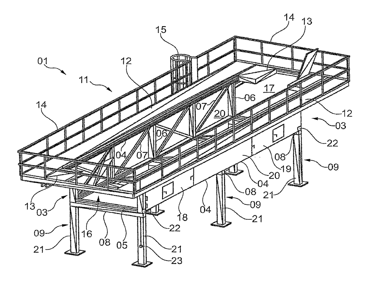
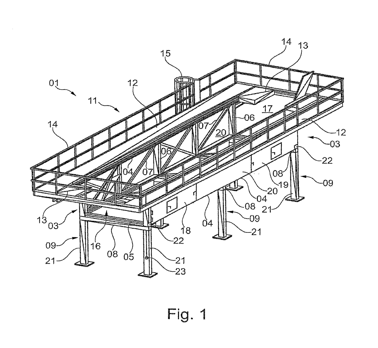
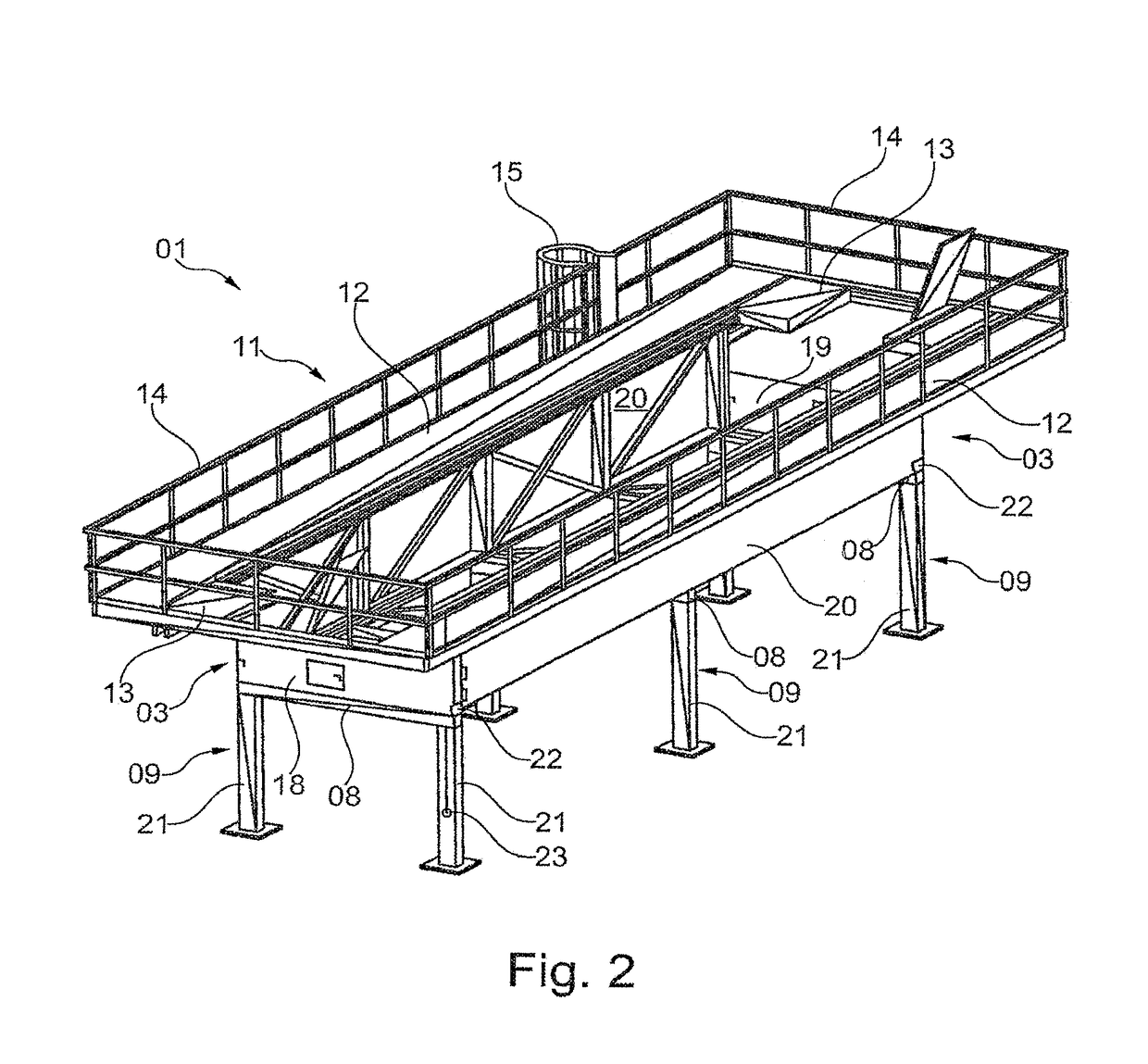
[0032]In FIG. 1, a perspective illustration of an overhead conveying device 01 is outlined in an exemplary embodiment. Here, the conveying device that belongs to the overhead conveying device 01 was chosen not to be illustrated. The same is located, as the person skilled in the art will easily be able to understand, in the center of the supporting framework 03, protruding well beyond the supporting framework 03, depending on the embodiment.

[0033]The supporting framework 03 is designed in the manner of a truss and comprises a multiplicity of supporting beam elements 04-07 that are welded together. The supporting framework 03 is formed by longitudinally oriented supporting beam elements 04, transversely oriented supporting beam elements 05, upright supporting beam elements 06 as well as diagonal supporting beam elements 07. Here, the supporting framework 03 having the supporting beam elements 04, 05, 06 and 07 is designed such that, when the conveying device has been mounted thereon, ...


PUM


Abstract

An overhead conveying device includes a conveying device mounted on supporting framework. The supporting framework and the conveying device form a conveying corridor. At least one securing element can be arranged at an input point and / or output point of the supporting framework, and the securing element can be moved between a securing position and an opening position. The securing element functions in the securing position as fall protection and at least partially blocks the initial cross-section and / or terminal cross-section of the conveying corridor. In the opening position, the securing element releases the initial cross-section and / or terminal cross-section of the conveying corridor for the transport of components with the help of the conveying device.

Description

CROSS-REFERENCE TO RELATED APPLICATIONS[0001]This application represents the national stage entry of PCT International Application No. PCT / EP2014 / 060534 filed May 22, 2014 and claims priority to German Patent Application No. 10 2013 213 223.9 filed Jul. 5, 2013. The contents of this application are hereby incorporated by reference as if set forth in their entirety herein.STATEMENT REGARDING FEDERALLY SPONSORED RESEARCH OR DEVELOPMENT[0002]Not applicable.FIELD OF THE INVENTION[0003]The invention relates to an overhead conveying device for integration in an assembly plant, which is suitable for transporting vehicle components.BACKGROUND OF THE INVENTION[0004]In assembly plants for manufacturing vehicles, different types of conveying devices as well as of overhead conveying devices are employed. Based on the fact that assembly plants are individually adjusted to each type of vehicle to be manufactured and that the conveying devices are correspondingly configured, the overhead conveying...

Claims


Application Information

Patent Timeline
IPC IPC(8): B65G47/00B65G43/00B65G41/00B62D65/18
CPCB62D65/18B65G41/006B65G43/00B65G2812/02108
Inventor HOSKER, TORSTEN
Owner HOSKER TORSTEN
Learn More