
Reduced cavitation oilfield choke

a technology of oilfield choke and cavitation, which is applied in the direction of sealing/packing, mechanical equipment, and wellbore/well accessories, etc., can solve the problems of reducing the effective life of the choke, the cost of manufacturing multiple disks with varying diameter staggered cylinders extending from the disk face is a significant drawback of these designs, and the design of multiple disks with varying diameter staggered cylinders is very costly to manufacture. , to achieve th

Active Publication Date: 2017-04-04
NAT OILWELL VARCO LP
View PDF20 Cites 1 Cited by
  • Summary
  • Abstract
  • Description
  • Claims
  • Application Information

AI Technical Summary

Benefits of technology

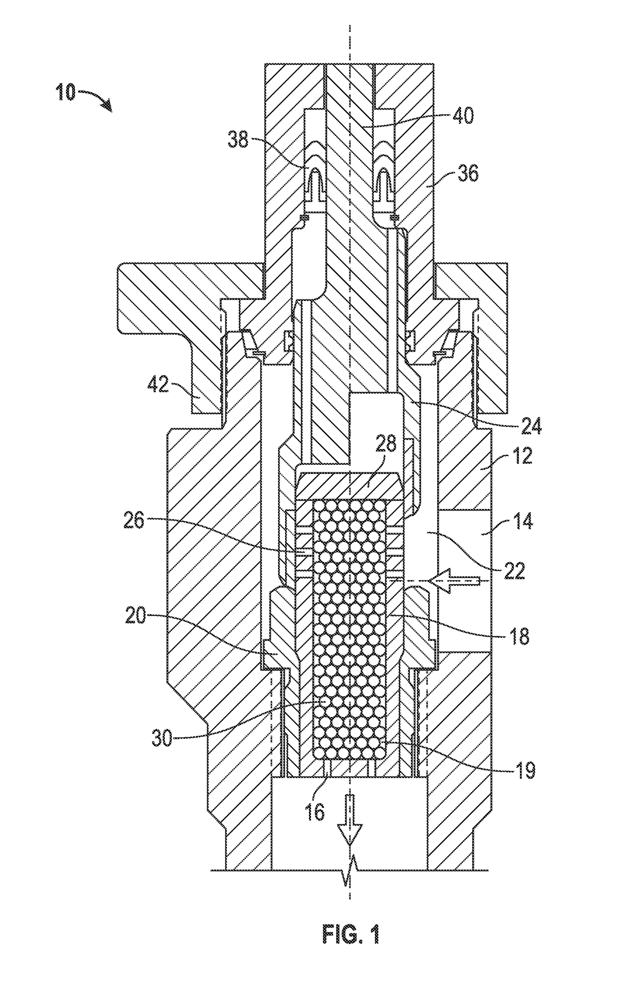
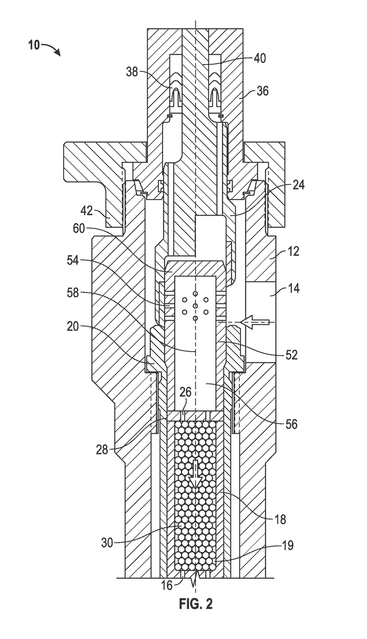
[0007]In one embodiment, a choke with reduced cavitation and / or flashing due to a high pressure fluids passing through the choke includes a housing having a high pressure inlet port and a low pressure outlet port, and a cage positioned within the housing and having a passage for passing fluid therethrough. A plurality of beads are each positioned in the cage, such that fluid flows between the cage and the beads and between the beads when passing through the cage. Fluid pressure is reduced by the fluid passing through the cage, thereby reducing cavitation.
[0009]ports to allow fluid to exit the cage; an actuator; a flow controller coupled to the actuator and configured to at least partially block the inlet ports into at least one of the cages; and a plurality of beads positioned within a bead cage, such that fluid flows between the bead cage and the plurality of beads and between the beads when passing through the bead cage, and fluid pressure is reduced while fluid passes through the bead cage.

Problems solved by technology

Chokes have been used for decades in oilfield operations to reduce the fluid pressure of high pressure flowing fluids, which often contain solids and / or chemicals which significantly reduce the effective life of the choke.
Multiple concentric cages or multiple stacked disks may be used to define a torturous path through a choke, but these designs are very costly to manufacture.
The cost of manufacturing multiple disks with varying diameter staggered cylinders extending from the disk face is a significant drawback to these designs.

Method used


Image

  • Reduced cavitation oilfield choke
  • Reduced cavitation oilfield choke
  • Reduced cavitation oilfield choke

Examples


Embodiment Construction

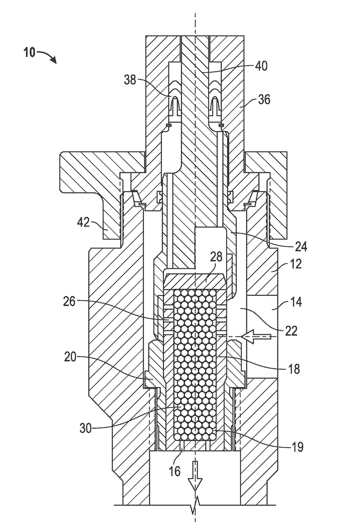
[0014]Referring to FIG. 1, a choke 10 includes a housing 12 having a high pressure inlet port 14 and a low pressure outlet port 16. A cage 18 is positioned within the housing and has an internal passage 19 for passing fluid therethrough. A choke seat 20 may be threaded to the housing 12, and the cage 18 may be shrink fit or otherwise secured to the choke seat. In FIG. 1, fluid enters through the side of the housing 12 and flows into an annulus 22 between a flow controller, such as the control sleeve 24, and the cage 18. The sleeve 24 may be moved axially up or down relative to the cage to open or close respective ones of a plurality of the ports 26 in the side of the cage. In FIG. 1, the left side of the drawing shows the sleeve fully closed, while the right side of the drawing shows the sleeve fully opened. When the sleeve exposes the ports 26, fluid flows into a cage and to the bottom of the choke, then out the port 16. Cap 36 encloses the upper end of sleeve 24, and seal ring 38 ...


PUM


Abstract

A choke with reduced cavitation and / or flashing due to a high pressure fluids passing through the choke includes a housing having a high pressure inlet port and a low pressure outlet port, and a cage positioned within the housing and having a passage for passing fluid therethrough. A plurality of beads are each positioned in the cage, such that fluid flows between the cage and the beads and between the beads when passing through the cage. Fluid pressure is reduced by the fluid passing through the cage, thereby reducing cavitation.

Description

CROSS REFERENCE TO RELATED APPLICATIONS[0001]The present invention is a 35 U.S.C. 371 application of PCT / US2013 / 028694 filed Mar. 1, 2013 claims priority to U.S. Provisional Application Ser. No. 61 / 610,622, filed Mar. 14, 2012, entitled “Reduced Cavitation Oilfield Choke”, the contents of all of which are incorporated herein by reference.STATEMENT REGARDING FEDERALLY SPONSORED RESEARCH OR DEVELOPMENT[0002]Not applicable.REFERENCE TO APPENDIX[0003]Not applicable.BACKGROUND OF THE INVENTION[0004]Chokes have been used for decades in oilfield operations to reduce the fluid pressure of high pressure flowing fluids, which often contain solids and / or chemicals which significantly reduce the effective life of the choke. The life of a choke is also significantly reduced by cavitation and / or flashing that occurs when high pressure fluids are decompressed.[0005]Various attempts have been made to reduce cavitation and flashing in chokes. Multiple concentric cages or multiple stacked disks may b...

Claims


Application Information

Patent Timeline
Patent Type & Authority Patents(United States)
IPC IPC(8): F16K47/08F16K3/24E21B34/02
CPCF16K47/08E21B34/02F16K3/246E21B34/025
Inventor MCCASKILL, LANE
Owner NAT OILWELL VARCO LP
Learn More