
Modular capillary bridge viscometer

a bridge and capillary technology, applied in the direction of direct flow property measurement, etc., can solve the problems of destroying the entire tubing piece, and affecting the accuracy of instruments

Active Publication Date: 2017-04-04
MALVERN INSTRUMENTS
View PDF13 Cites 0 Cited by
  • Summary
  • Abstract
  • Description
  • Claims
  • Application Information

AI Technical Summary

Benefits of technology

This patent describes a capillary bridge viscometer that can measure the viscosity of liquids, as well as a supporting structure for the bridge arms and a balance detector to measure the movement of the bridge. The invention allows for easy assembly and replacement of the bridge supporting structure, and ensures even pressure on the bridge arms. The technical effects of this patent are an improved accuracy and reliability of viscosity measurements and a simplified and flexible design for laboratory use.

Problems solved by technology

This can be extremely inconvenient and may also require the instrument to be returned to the manufacturer for qualified servicing.
These changes are typically ignored because of the inconvenience and because the length difference involved can be physically too small to allow an accurate adjustment to be accurately accomplished, and the result can be a decrease in instrument performance.
These can be over-tightened because of leaking or they may become stuck in the fitting, ruining the entire piece of tubing.
Improper installation can also result in a space between one end of the tube and the fitting, creating a dead volume which can increase the band broadening of the detector.

Method used


Image

  • Modular capillary bridge viscometer
  • Modular capillary bridge viscometer
  • Modular capillary bridge viscometer

Examples


Embodiment Construction

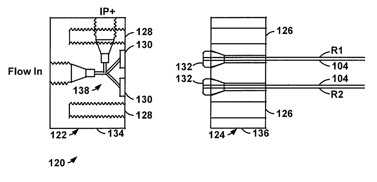
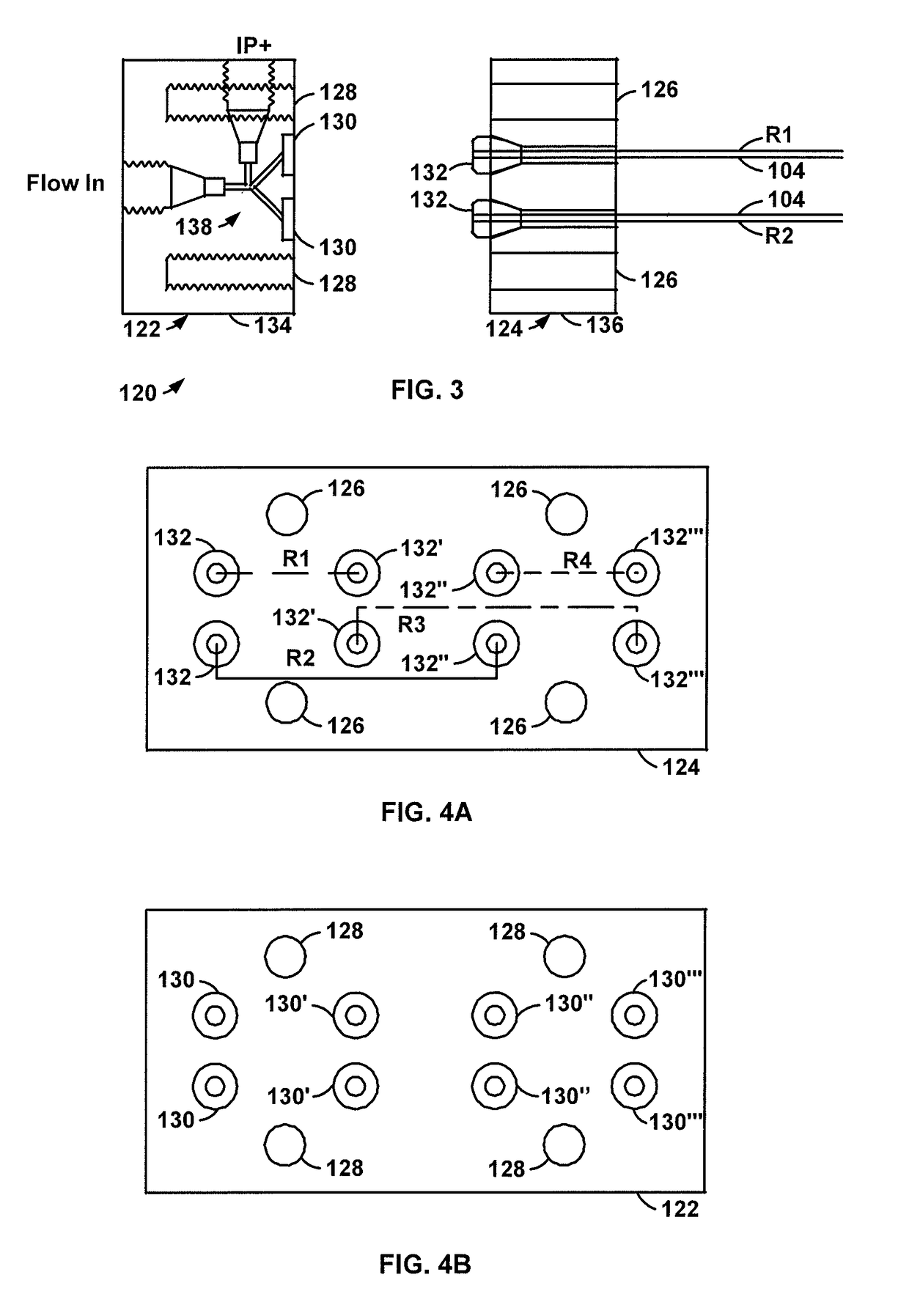
[0023]Referring to FIGS. 3-7, an illustrative capillary bridge viscometer 120 according to the invention includes a bulkhead 122 and a bridge module 124. The bulkhead includes ports 130 that are positioned to mate with corresponding hydraulic connectors 132 on the bridge module, which supports the bridge tubing. The ports and connectors define a set of removable connections between the bulkhead and the bridge module. This arrangement allows the bridge module to be quickly changed for different experiments or if it becomes fouled, and the bridge module can even be disposable.

[0024]In the illustrative embodiment, the ports are cylindrical openings in the bulkhead block and the connectors are flangeless low-pressure ferrules, such as are available from IDEX corporation of Lake Forest, Ill. under part number P-200NX. One of ordinary skill would of course recognize that many other suitable types of removable hydraulic fittings could also be used to provide removable connections between t...


PUM

PropertyMeasurementUnit
HPLCaaaaaaaaaa
resistanceaaaaaaaaaa
flow rateaaaaaaaaaa

Abstract

A capillary bridge viscometer (120), comprises at least two at least generally balanced bridge arm conduits (R1, R2) a bulkhead supporting structure (122,134) supporting removable connection portions for each of a plurality of the arms in a bridge configuration, a bridge supporting structure (124,136) supporting the bridge arm conduits (R1,R2) and supporting two further removable connection portions (132) for each of the bridge arm conduits, wherein each of the further removable connection portions (132) supported by the bridge supporting structure are positioned to mate with a corresponding one of the removable connection portions (130) supported by the bulkhead supporting structure concurrently to hydraulically connect the bridge arm conduits in the bridge configuration; and a balance detector having hydraulic connections for connection between first and second differential detection points in the bridge when the removable connection portions on the bridge are mated to corresponding ones of the removable connection portions supported by the bulkhead supporting structure.

Description

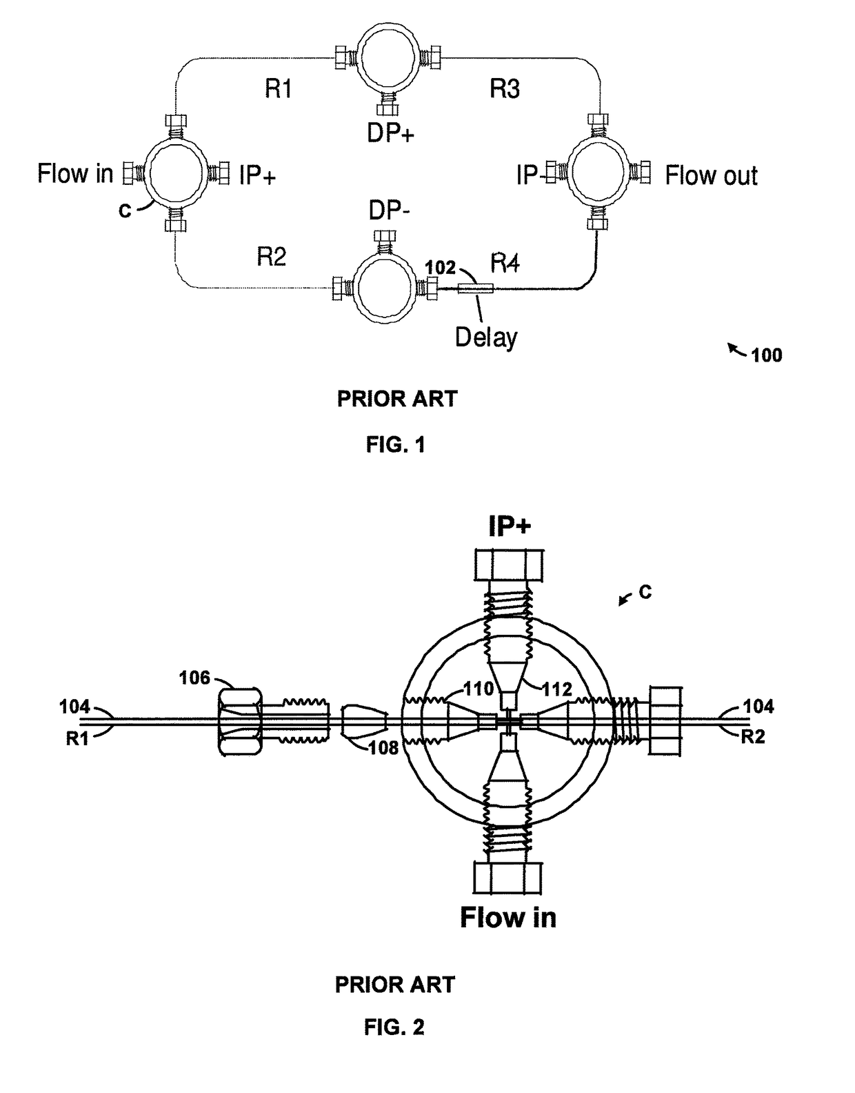
[0001]This application claims priority to provisional application No. 61 / 385,955, filed Sep. 23, 2010.FIELD OF THE INVENTION[0002]The invention relates, in one general aspect, to capillary viscometers, including capillary bridge viscometers with a modular design.BACKGROUND OF THE INVENTION[0003]Referring to FIG. 1, multi-capillary viscometers can introduce some type of delay unit in order to make a differential measurement while a sample is being measured. An illustrative prior art four-capillary viscometer 10, for example, includes four pieces of tubing or capillaries connected in a series-parallel configuration to form the hydraulic equivalent of a Wheatstone-Bridge in electronics. These tubing or capillaries in the arms of the bridge are often referred to as R1, R2, R3, and R4 because they are in effect hydraulic resistors. The delay unit 102 is placed in series with one of the capillaries and usually it consists of a column packed with or containing a material or solvent that wi...

Claims


Application Information

Patent Timeline
Patent Type & Authority Patents(United States)
IPC IPC(8): G01N11/08
CPCG01N11/08
Inventor CLARKE, PAUL G.MURPHY, MICHAEL P.
Owner MALVERN INSTRUMENTS
Learn More