Facility and method for depositing a film of ordered particles onto a moving substrate

a technology of ordered particles and moving substrates, which is applied in the direction of liquid surface applicators, coatings, etc., can solve the problems of non-homogeneous film, insufficient pressure force exerted by these particles, and inability to order particles before their own, etc., to achieve the effect of great simplicity of adjustmen

Inactive Publication Date: 2016-11-29
COMMISSARIAT A LENERGIE ATOMIQUE ET AUX ENERGIES ALTERNATIVES
View PDF6 Cites 0 Cited by
  • Summary
  • Abstract
  • Description
  • Claims
  • Application Information

AI Technical Summary

Benefits of technology

[0021]By obtaining satisfactory ordering, as soon as the initiation phase, no portion of the particles or of the substrate has to be cleared, implying that it is not necessary to isolate the portion of the finished product stemming from the initiation phase. The production costs are thereby substantially reduced. They are also reduced by the simplification of the method, which no longer requires any purging phase aiming at depositing a portion of the non-compliant film, and at clearing it. Further, the risks of dissemination of the particles is also reduced.
[0022]Thus, the invention is remarkable in that, in a simple and efficient way, it gives the possibility of avoiding the formation of clusters, first isolated and then grouped in an unsatisfactory way, as this was the case in the prior art. The suction nozzles are actually a simple system for stretching the film laterally, towards each of the two edges, and ensuring that the film produced has, in every point, a so-called <<compact hexagonal>> structure, in which each particle is surrounded and in contact with six other particles in contact with each other.
[0026]Globally, these retention means give the possibility of reducing the size of the transfer area during its initial filling, during the initiation phase. Several advantages result from this.
[0027]First of all, this reduces the surface area on which the nozzles assist the particles for ensuring their ordering. The control of these nozzles is thus more simple to be achieved. Further, this gives the possibility of facilitating the ordering, in the sense that the pressure exerted on the particles of the transfer area, by the particles located upstream from this area, is more effective for forcing the particles to be ordered when the latter extend over a shorter length. It has been seen that the beneficial effects mentioned above are even more significant when an upstream end of these temporary retention means is located at a distance of less than 20 mm from the entry of the transfer area.
[0029]Preferably, said temporary retention means for the particles assume the form of a layer in a hydrophobic material, floating at the surface of the carrier liquid. This solution proves to be simple and effective in order to form a barrier to the particles which can neither pass above the layer because of the hydrophobicity which prevents wetting of the upper surface of the layer, nor pass between the layer and the carrier liquid by means of the small thickness of the barrier which allows easy deformation in order to adapt to the shape variations of the surface of the carrier liquid. Moreover, this layer has a thickness preferentially comprised between few microns and a few tens of microns for example between 50 and 100 μm.
[0034]Preferably, said nozzles are alternately actuated so as to attract the particles present in the transfer area towards either one of the two side edges, alternately. Simultaneous actuation may nevertheless be contemplated, without departing from the scope of the invention. However, alternate actuation which may integrate pause periods between the changes of nozzles, is preferred for its greater simplicity for adjustment. Further, the pause periods allow the particles to continue to accumulate, thus allowing pressurization of the particles already present.

Problems solved by technology

In all these embodiments of the prior art, and in particular in the one applying the tilted ramp, a problem is encountered which occurs at the moment of putting the facility into operation.
However, these particles do not have the possibility of being ordered before their entry into the transfer area, since the front of particles does not yet sufficiently move up upstream.
If these clusters of particles end up by joining up together during the initial filling of the transfer area, when the filling level of the latter becomes a high level, voids are formed between these clusters, which makes the film non-homogeneous and therefore unsatisfactory.
Nevertheless, the pressure forces exerted by these particles very often prove to be insufficient for filling the voids between the gathered clusters, because of the strong internal stresses within these clusters which prevent reordering of the particles.
In such a case, the quality of the film is of course estimated to be also unsatisfactory.
Therefore, the film of particles located in the transfer area before setting the facility into operation, has quality defects which require it to be cleared by deposition on a dedicated substrate.
This is first of all expressed by unnecessary consumption of particles and of substrates, having an impact on the production costs.
These same costs are also increased due to the complexification of the method, which therefore requires a purging phase aiming at depositing the portion of the non-compliant film, and then of clearing it.
Further, the risks of dissemination of the particles are amplified, notably when the latter are of small dimensions for example of less than 400 nm.

Method used


Image

  • Facility and method for depositing a film of ordered particles onto a moving substrate
  • Facility and method for depositing a film of ordered particles onto a moving substrate
  • Facility and method for depositing a film of ordered particles onto a moving substrate

Examples


Embodiment Construction

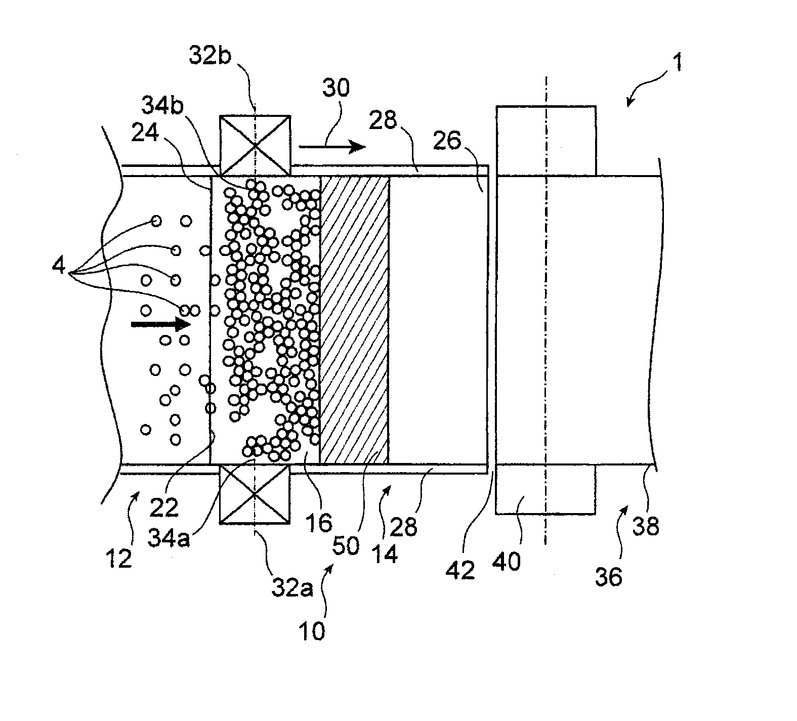
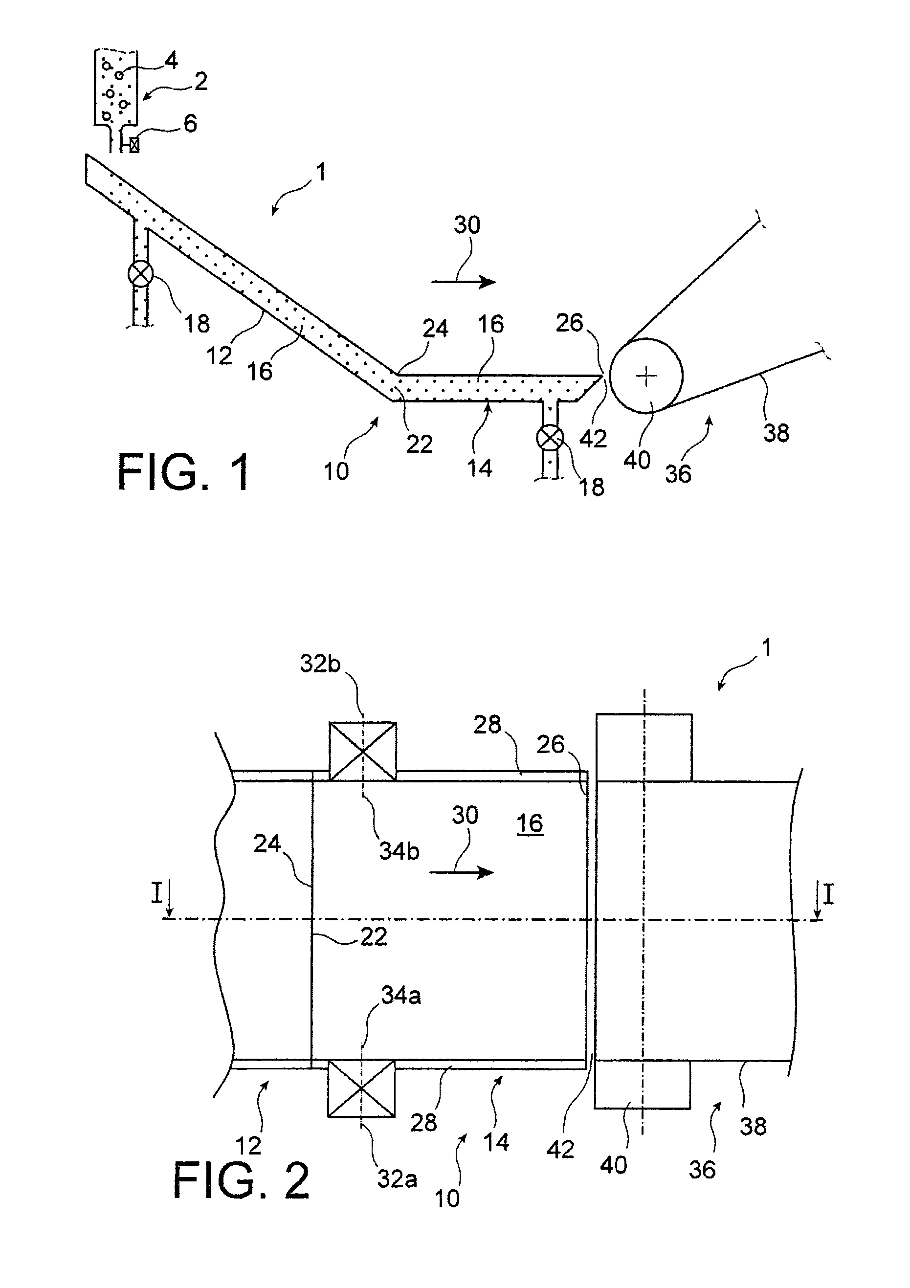
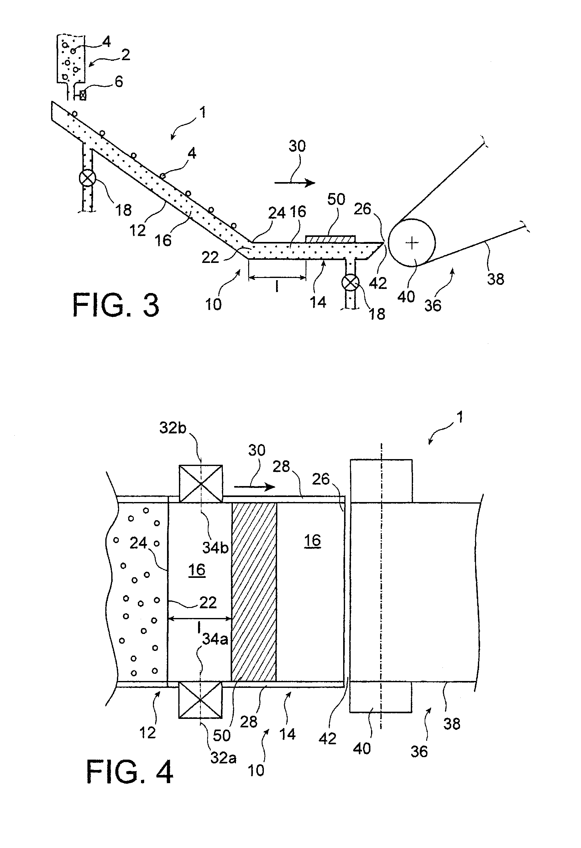
[0043]Referring first of all to FIGS. 1 and 2, a facility 1 for depositing a film of ordered particles onto a moving substrate may be seen.

[0044]The facility includes a device 2 for dispensing particles 4, the size of which may be comprised between a few nanometers and several hundred micrometers. The particles, preferably of spherical shape, may for example be silica particles.

[0045]More specifically, in the preferred embodiment, the particles are silica spheres with a diameter of about 1 μm, stored in a solution in the dispensing device 2. The proportion of the medium is of about 7 g of particles for 200 ml of solution, here butanol. Naturally, for reasons of clarity, the particles illustrated in the figures adopt a diameter greater than their actual diameter.

[0046]The dispensing device 2 has a controllable injection nozzle 6, with a diameter of about 500 μm.

[0047]The facility also includes a conveyor 10 of liquid, integrating a tilted ramp 12 for circulation of the particles, and...


PUM

PropertyMeasurementUnit
distanceaaaaaaaaaa
particle sizeaaaaaaaaaa
thicknessaaaaaaaaaa

Abstract

A facility for depositing a film of ordered particles onto a moving substrate, the facility including: a transfer area including an entry of particles and an exit of particles spaced apart from each other by two side edges facing each other, retaining a carrier liquid on which the particles float, a capillary bridge ensuring connection between the carrier liquid contained in the transfer area and the substrate, and a plurality of suction nozzles capable of attracting the particles towards its two side edges.

Description

TECHNICAL FIELD[0001]The invention relates to the field of facilities and methods for depositing a film of ordered particles, onto a moving substrate.[0002]More specifically, it relates to the deposition of a film of ordered particles, preferably of the monolayer type, the particle size of which may be comprised between a few nanometers and several hundred micrometers. The particles, preferably of spherical shape, may for example be silica particles.[0003]The invention has many applications, in particular in the field of fuel cells, optics, photonics, polymeric coatings, chips, MEMs, surface structuration for organic electronics and photovoltaics, etc.STATE OF THE PRIOR ART[0004]Such methods and facilities aiming at depositing a film of ordered particles onto a moving substrate are known from the prior art, the latter substrate may be flexible or rigid.[0005]Generally, a transfer area is provided, supplied with particles which float in a carrier liquid contained in this same transfe...

Claims


Application Information

Patent Timeline
Patent Type & Authority Patents(United States)
IPC IPC(8): B05C19/02B05D1/20B05D1/00B05C19/00
CPCB05C19/02B05C19/00B05D1/00B05D1/20B05D1/204B05D2252/02
Inventor DELLEA, OLIVIERFUGIER, PASCALCORONEL, PHILIPPE
Owner COMMISSARIAT A LENERGIE ATOMIQUE ET AUX ENERGIES ALTERNATIVES
Why Eureka
Try Eureka