Printed piezoelectric pressure sensing foil

a piezoelectric and pressure sensing technology, applied in the direction of instruments, electric digital data processing, digital data processing details, etc., can solve the problems of inconvenient pressure sensing, limited tracking resolution to the space between the sensing lines, and standard resistive touch panel concept not suitable for pressure sensing

Active Publication Date: 2017-04-04
JOANNEUM RES FORSCHUNGS GMBH
View PDF7 Cites 22 Cited by
  • Summary
  • Abstract
  • Description
  • Claims
  • Application Information

AI Technical Summary

Problems solved by technology

In addition, the separation of ‘touch’ and ‘pen’ inputs is not easily possible.
Although this approach is inexpensive and energy-efficient, the tracking resolution is limited to the space between the sensing lines.
However, the standard resistive touch panel concept is not suitable for pressure sensing.
However, capacitive sensing can only measure the touch location (resolution is limited by touch area).
It is not suitable for pressure sensing.
Another major disadvantage of this technique is that it relies on the dielectric properties of the human body; thus, stylus or objects cannot be tracked.
Such devices are expensive due to the costs of the required inorganic piezoelectric materials and the involved costly assembling process.
They provide only limited user interaction as for example the detection of a motion-less finger is impossible.
Although some of the above mentioned sensor concepts provide multi-touch sensing capabilities, it is often not possible to track the pressure of the input efficiently and accurately.

Method used


Image

  • Printed piezoelectric pressure sensing foil
  • Printed piezoelectric pressure sensing foil
  • Printed piezoelectric pressure sensing foil

Examples


Embodiment Construction

[0022]Exemplary embodiments of the invention will now be described with reference to the drawings.

Introduction

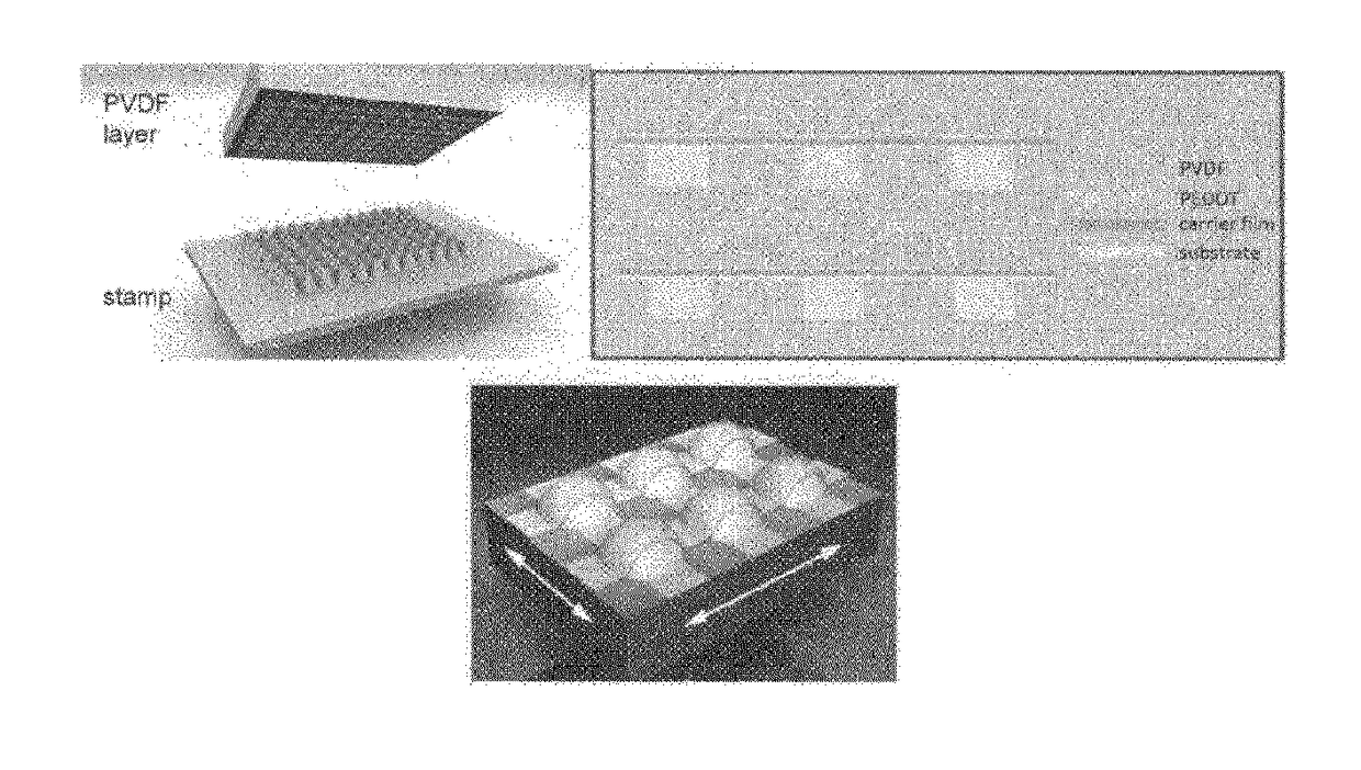
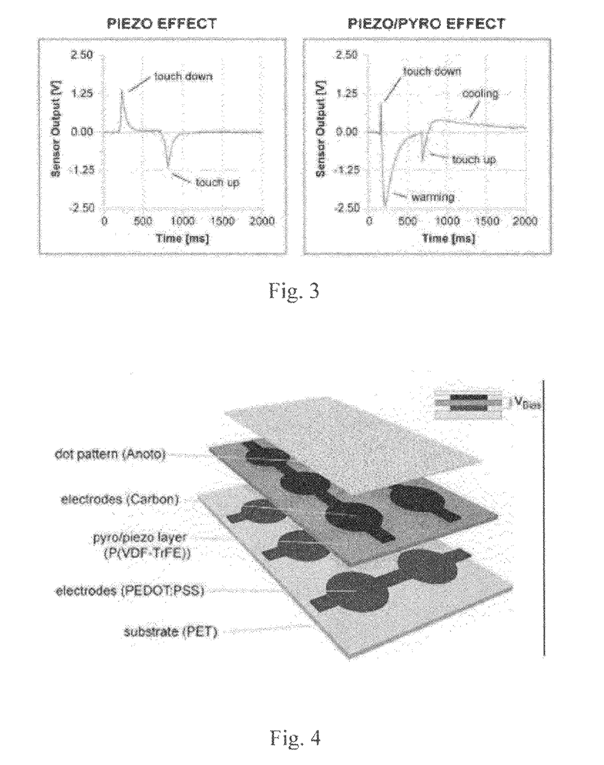
[0023]In an embodiment of the present invention, there is provided a pressure-sensing input device that is based on a ferroelectric material that supports both pyro- and piezoelectric effects. The ferroelectric material can be used for sensing pressures changes on large, flat and / or bended surfaces. The input device has a sandwich structure of four layers that can be printed easily on any material. This material can be used in combination with a high-resolution optical based sensing foil, such as described in US 2011 / 0310066 A1, or an optical Stytlus as described in US 2012 / 0127110 A1.

[0024]The input device supports both hand and pen input tracking. The foil implementing the device is bendable, energy-efficient, and it can be produced easily in a printing process.

[0025]The input device also supports a hovering mode based on the pyroelectric effect.

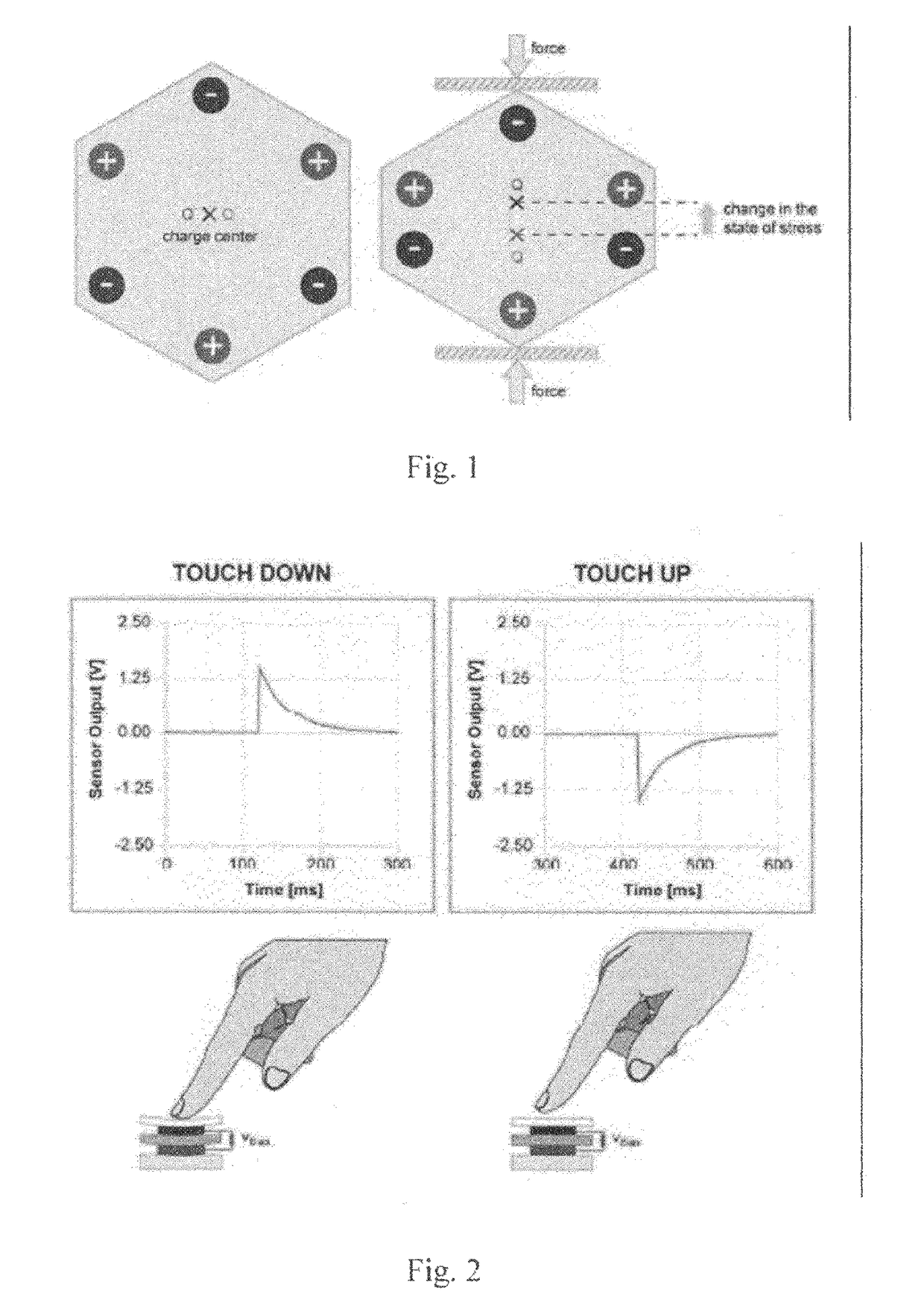
Piezoelectric Effect

[0026]P...


PUM


Abstract

There is provided an sensing device, comprising: a substrate; a sensor ink printed onto the substrate; a conductive polymer ink printed onto the sensor ink; a conductive carbon paste formed on the polymer ink; and a conductive silver ink printed on the conductive carbon paste. There is also provided a sensing device for processing a signal generated by the input device, the sensing device comprising: an operational amplifier to amplify the signal; a filter to filter signal noise from the signal; an adder to apply an offset and attenuation to the signal; a microcontroller comprising an analog to digital converter to convert the signal into a digital output signal.

Description

BACKGROUND[0001]Over recent years, touch sensing devices have become more and more important. Touch sensing devices can be divided into three different categories: optical, resistive, and capacitive tracking devices.[0002]Optical touch solutions are highly dependent on ambient lighting and the material of the tracking object. In addition, the separation of ‘touch’ and ‘pen’ inputs is not easily possible.[0003]Resistive array-based sensors usually consist of two layers of conductive material, one with horizontal lines and one with vertical lines. When a user touches the surface, the horizontal and vertical lanes are alternately connected, enabling the flow of current. Although this approach is inexpensive and energy-efficient, the tracking resolution is limited to the space between the sensing lines. Alternatively, plane-type conductors with well-defined resistivity are used as top and bottom electrodes. The touch signal is measured by applying a voltage to one of the electrodes and ...

Claims


Application Information

Patent Timeline
Patent Type & Authority Patents(United States)
IPC IPC(8): G06F3/043G06F1/16G06F3/041
CPCG06F3/0433G06F1/16G06F3/0414G06F3/0416G06F3/0418G06F2203/04104G06F2203/04106G06F3/04166G06F3/04186
Inventor ZIRKL, MARTINSTADLOBER, BARBARAHALLER, MICHAELGREINDL, PATRICKRENDL, CHRISTIAN
Owner JOANNEUM RES FORSCHUNGS GMBH
Why Eureka
Try Eureka