Wire harness

a wire harness and wire technology, applied in the direction of electric/fluid circuits, vehicle components, transportation and packaging, etc., can solve the problems of unstable flexure performance before and after the change of parts, difficult to cope with the issue, etc., to improve the adherence with the waterproofing member, improve the adherence, and maintain the effect of waterproofness

Active Publication Date: 2017-04-11
YAZAKI CORP
View PDF11 Cites 3 Cited by
  • Summary
  • Abstract
  • Description
  • Claims
  • Application Information

AI Technical Summary

Benefits of technology

[0034]According to the present invention described in (1), because the exterior member that has one or a plurality of irregular portions in the pipe axial direction is adopted, if the irregular portions are arranged at desired positions, an effect is played that the wire harness can be wired, even if wiring space varies at different sites, for example, there is a small space partially. Further, according to the present invention, because the structure that the shape converting part is arranged between the first irregular pipe part and the second irregular pipe part is adopted in the irregular portion, for example, when it is intended to exhibit different flexure performances at the side of the first irregular pipe part and at the side of the second irregular pipe part, the electrical pathway can be fixed at the shape converting part. As a result, an effect is played that the different flexure characteristics before and after the shape converting part can be exhibited in a stable state.
[0041]According to the present invention described in (8), because the dropout of the waterproofing member is prevented, an effect is played that it is possible to maintain the adherence with the waterproofing member.

Problems solved by technology

However, when the bellows pipe part is watched, because the cross section of the above bellows pipe part is uniform, if the wiring space varies at different sites, there is a problem which is that it is difficult to cope with the issue.
Further, because the cross section is uniform, if it is intended to exhibit different flexure performances, there is also a problem which is that it is difficult to cope with the issue.
However, because the shape of the changed part becomes distorted, and the changed part itself has flexibility, it is found that there is a trouble which is that the flexure performance before and after the changed part becomes unstable.
However, preventive measures against water invasion at the terminals of the exterior member are insufficient.
Thus, the inventors of the present application attempted to attach, for example, rubber boots to the terminals of the exterior member to cover the terminals of the exterior member, but because those parts of the exterior member that include the terminals, namely, the parts corresponding to the harness terminals have a bellows pipe shape, it is found that there is a problem which is that adherence to waterproofing members such as the boots is bad.

Method used


Image

  • Wire harness
  • Wire harness
  • Wire harness

Examples


embodiment 1

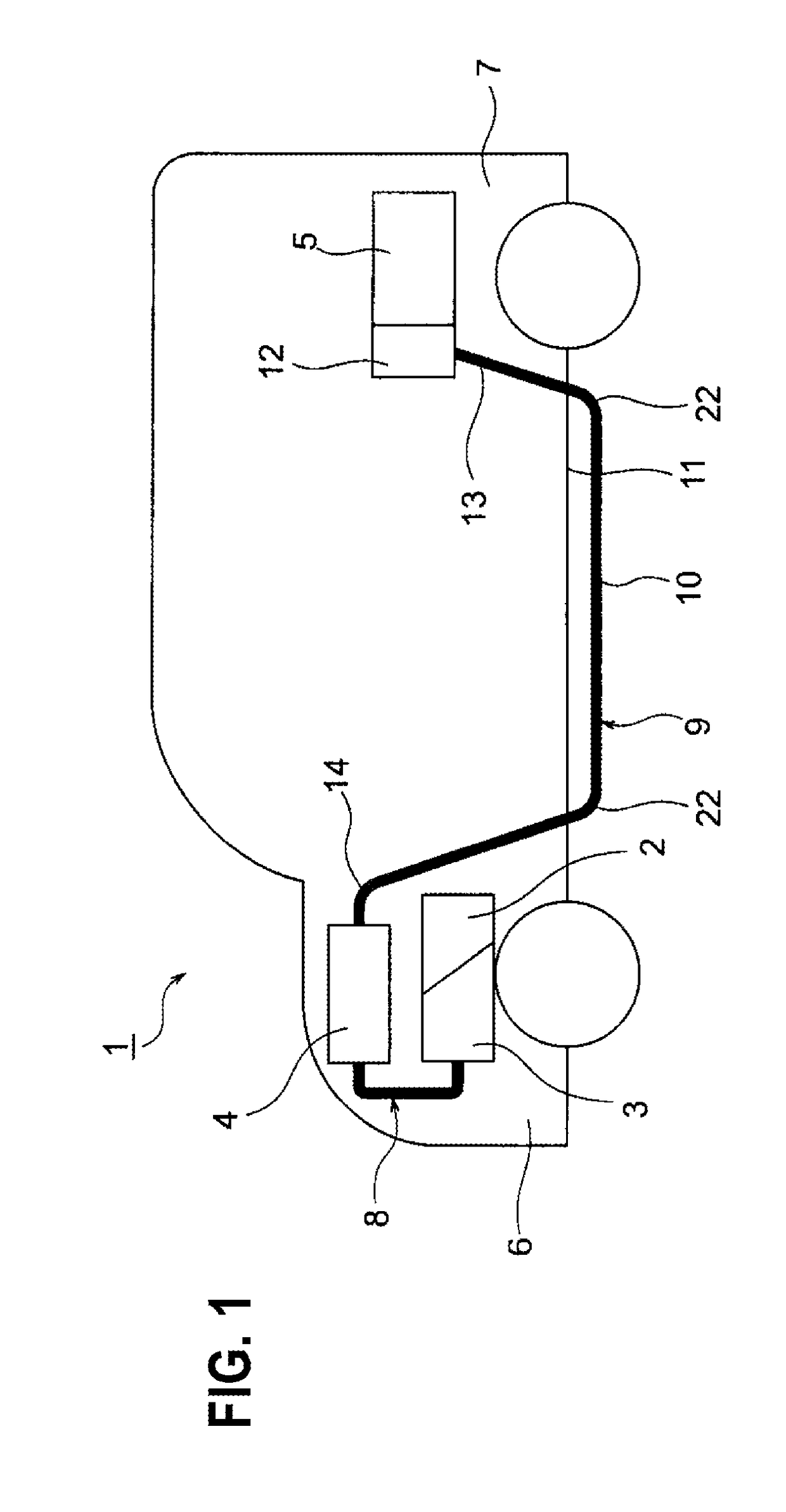
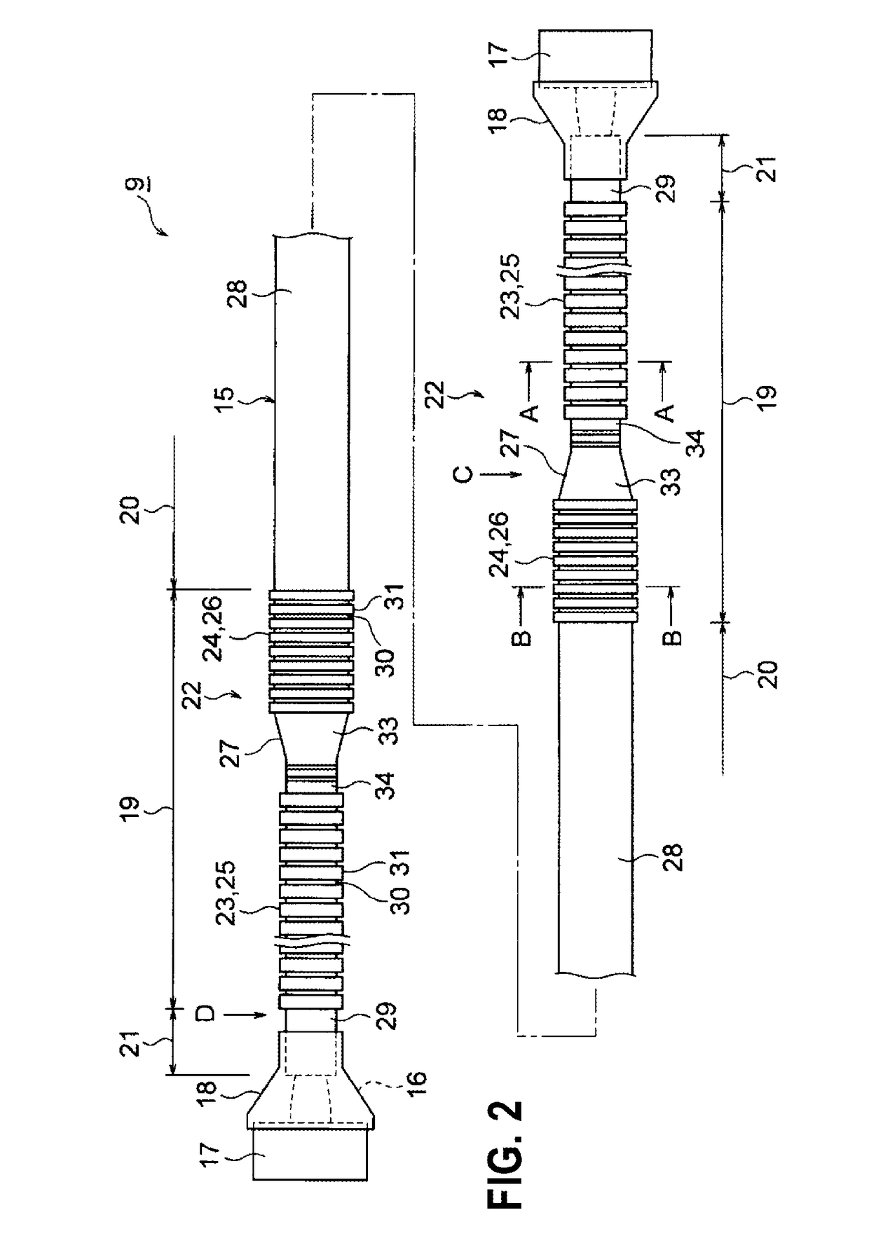
[0059]An embodiment 1 is described with reference to the figures as follows. FIG. 1 is a schematic view which indicates that a wire harness of the present invention is wired. FIG. 2 is a top view which indicates the constitution of the wire harness. FIGS. 3A and 3B include sectional views of the wire harness, in which FIG. 3A is an A-A line sectional view of FIG. 2, and FIG. 3B is a B-B line sectional view of FIG. 2.

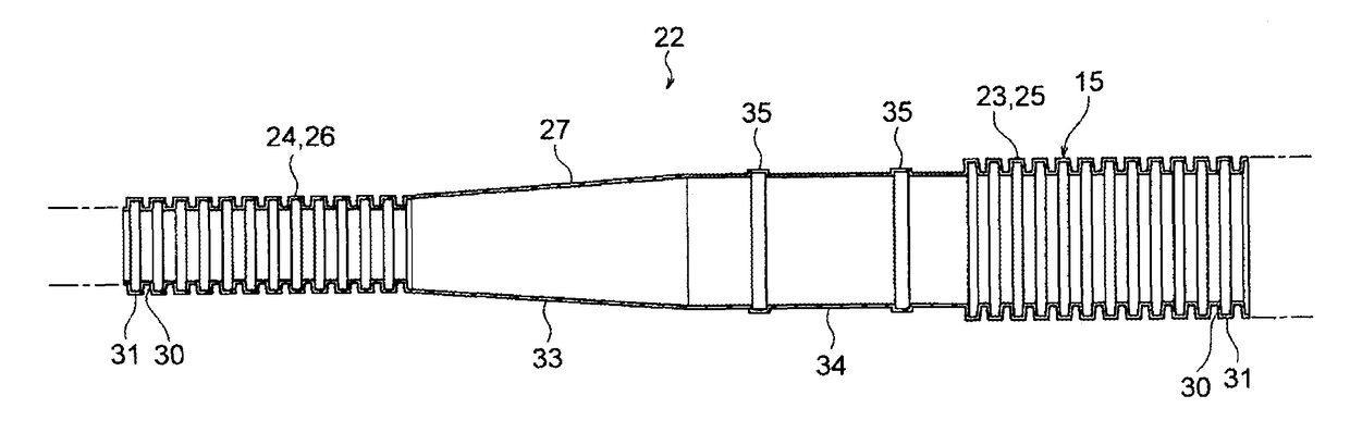
[0060]FIG. 4 is a perspective view of portions corresponding to an arrow C of an exterior member of FIG. 2. FIGS. 5A and 5B include sectional views of the exterior member of FIG. 4, in which FIG. 5A is an E-E sectional view, FIG. 5B is a view watched from an arrow F in FIG. 4, and FIG. 5C is a view watched from an arrow G in FIG. 4. FIG. 6A is a perspective view of portions corresponding to arrow D of the exterior member of FIG. 2, and FIG. 6B is a figure of a variation of FIG. 6A.

[0061]In the present embodiment, the present invention is applied to a wire harness which i...

embodiment 2

[0110]An embodiment 2 is described with reference to the figures as follows. FIGS. 7A and 7B are sectional views which indicates a first variation of the exterior member of FIGS. 3A and 3B. Components that are substantially identical with those in the above-mentioned embodiment 1 are given identical signs, and their detailed description is omitted.

[0111]In FIGS. 7A and 7B, a wire harness 9′ according to the present invention includes an exterior member 15′, and a high voltage electrical pathway 16 (electrical pathway) which is accommodated and protected in the exterior member 15′. The exterior member 15′ is a resin molded article, and is formed with irregular portions 22′ which are features of the present invention in ranges that are set as bendable wiring ranges 19 in the exterior member 15′.

[0112]The irregular portion 22′ has a first irregular pipe part 25′, a second irregular pipe part 26′, and a shape converting part 27′. The first irregular pipe part 25′ and the second irregula...

embodiment 3

[0115]An embodiment 3 is described with reference to the figures as follows. FIGS. 8A-8C are sectional views which indicate a second variation of the exterior member of FIGS. 3A and 3B. Components that are substantially identical with those in the above-mentioned embodiment 1 are given identical signs, and their detailed description is omitted.

[0116]In FIGS. 8A-8C, a wire harness 9″ according to the present invention includes an exterior member 15″, and a high voltage electrical pathway 16 (electrical pathway) which is accommodated and protected in the exterior member 15″. The exterior member 15″ is a resin molded article, and is formed with irregular portions 22″ which are features of the present invention in ranges that are set as bendable wiring ranges 19 in the exterior member 15″.

[0117]The irregular portion 22″ has a first irregular pipe part 25″, a second irregular pipe part 26″, and a shape converting part 27″. The first irregular pipe part 25″ and the second irregular pipe p...


PUM


Abstract

A wire harness includes a plurality of electrical pathways or a plurality of circuits of electrical pathways, and an exterior member into which the electrical pathways are inserted and which protects the electrical pathways. The exterior member is formed by being resin molded into a single pipe-like shape, and has at least one of irregular portions in a pipe axial direction. The irregular portion has a first irregular pipe pan, a second irregular pipe part which is different in shape from the first irregular pipe part and a shape converting part which links the first irregular pipe part and the second irregular pipe part. The shape converting part is formed as a part which extends a predetermined length in the pipe axial direction to straightly wire the wire harness.

Description

CROSS-REFERENCE TO RELATED APPLICATIONS[0001]This application claims the benefit of Japanese Patent Applications Nos. 2014-154547 (filed on Jul. 30, 2014) and 2014-154548 (filed on Jul. 30, 2014), the contents of which are incorporated herein by reference.BACKGROUND[0002]1. Technical Field[0003]The present invention relates to a wire harness which includes an electrical pathway and an exterior member. The present invention relates to a wire harness which includes a plurality of electrical pathways or a plurality of circuits of electrical pathways, and an exterior member into which the electrical pathways are inserted and which protects the electrical pathways, and particularly to a wire harness which has an exterior member that is formed of resin into a single pipe-like shape and that has one or a plurality of irregular portions in the pipe axial direction.[0004]2. Related Art[0005]A traditional wire harness is known which electrically connects, for example, high voltage apparatuses...

Claims


Application Information

Patent Timeline
Patent Type & Authority Patents(United States)
IPC IPC(8): B60R16/02
CPCB60R16/0215
Inventor OGA, TATSUYAADACHI, HIDEOMI
Owner YAZAKI CORP
Why Eureka
Try Eureka