Power amplifier bias signal multiplexing

a power amplifier and bias signal technology, applied in the field of electronics, can solve problems such as unfavorable routing complexity, and achieve the effect of facilitating transmission of an amplified rf signal

Active Publication Date: 2017-04-11
SKYWORKS SOLUTIONS INC
View PDF7 Cites 4 Cited by
  • Summary
  • Abstract
  • Description
  • Claims
  • Application Information

AI Technical Summary

Problems solved by technology

Multiple input / output lines can result in undesirable routing complexity.

Method used


Image

  • Power amplifier bias signal multiplexing
  • Power amplifier bias signal multiplexing
  • Power amplifier bias signal multiplexing

Examples


Embodiment Construction

[0029]While certain embodiments are described, these embodiments are presented by way of example only, and are not intended to limit the scope of protection. Indeed, the novel methods and systems described herein may be embodied in a variety of other forms. Furthermore, various omissions, substitutions and changes in the form of the methods and systems described herein may be made without departing from the scope of protection.

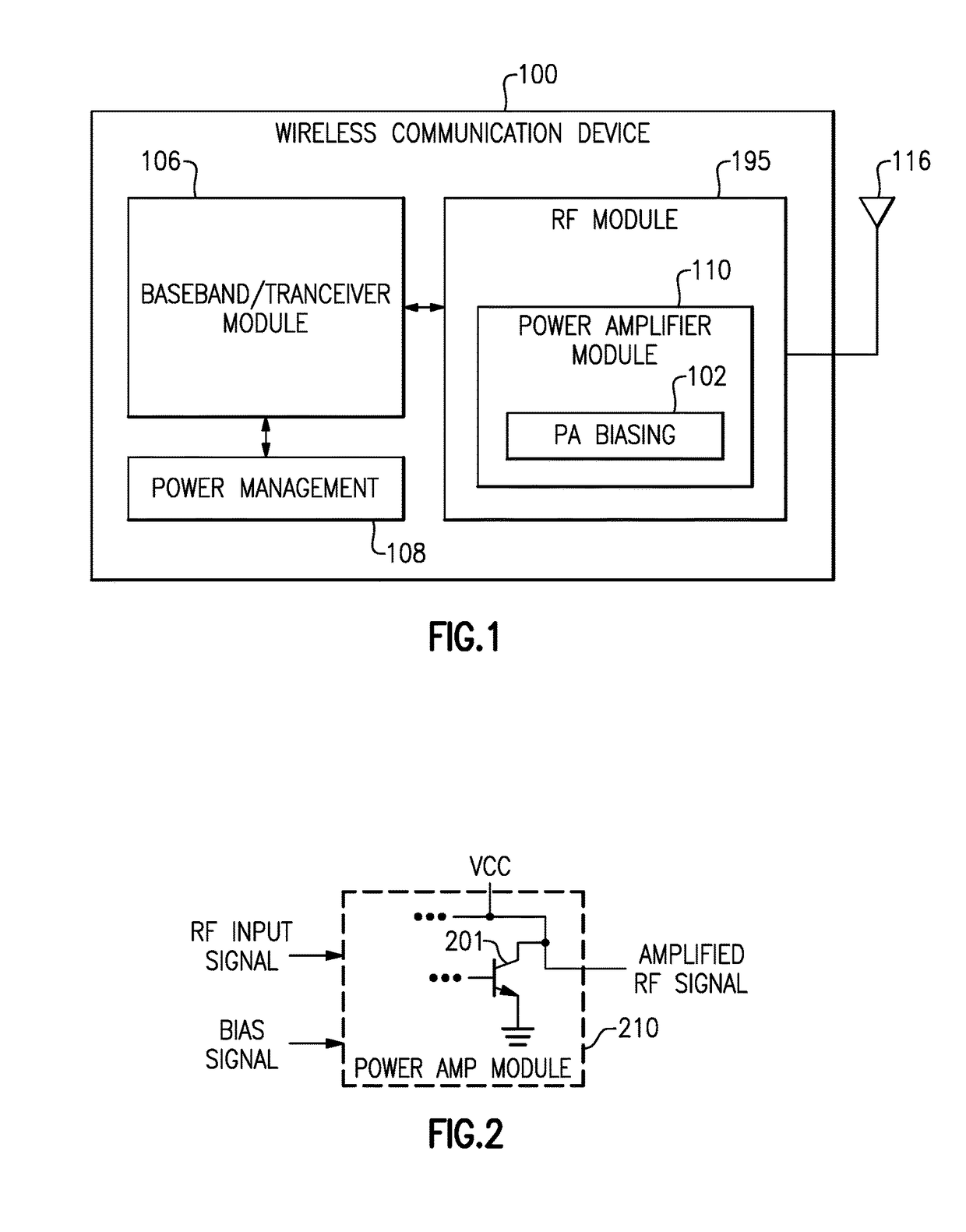
[0030]FIG. 1 is a block diagram illustrating an embodiment of a wireless communication device 100. Although described with particular reference to a wireless communication devices, such as a mobile telephones or other mobile computing devices, systems and methods for multiplexing bias signals in power amplifier systems as described herein may advantageously be applicable in any device or system including a power amplifier, or other device for which simplified routing of transmission lines may be desirable. Bias signal multiplexing as described herein may be im...


PUM


Abstract

A power amplifier (PA) system includes an amplifying transistor having a base, a collector, and an emitter. The PA system further includes a radio-frequency (RF) input configured to receive an RF input signal having an RF component and a DC bias component, a bias circuit coupled to the base of the amplifying transistor, and a bias tee circuit configured to receive the RF input signal and pass at least a portion of the DC component to the bias circuit and at least a portion of the RF component to the base of the amplifying transistor.

Description

RELATED APPLICATIONS[0001]This application claims priority to U.S. Provisional Application No. 62 / 116,032, filed Feb. 13, 2015, and entitled POWER AMPLIFIER BIAS SIGNAL MULTIPLEXING, the disclosure of which is hereby incorporated by reference in its entirety.BACKGROUND[0002]Field[0003]The present disclosure generally relates to the field of electronics, and more particularly, to radio-frequency (RF) modules and devices.[0004]Description of Related Art[0005]RF modules and dies, including power amplifiers, may have various inputs and outputs associated therewith. Multiple input / output lines can result in undesirable routing complexity.SUMMARY[0006]In some implementations, the present disclosure relates to a power amplifier (PA) system comprising an amplifying transistor having a base, a collector, and an emitter, a radio-frequency (RF) input configured to receive an RF input signal having an RF component and a DC bias component, a bias circuit coupled to the base of the amplifying tra...

Claims


Application Information

Patent Timeline
Patent Type & Authority Patents(United States)
IPC IPC(8): H03F3/06H03F1/02H03F3/24H03F3/19H03F3/21H03F3/72
CPCH03F3/211H03F1/0261H03F3/19H03F3/245H03F3/72H03F2200/111H03F2200/451H03F2200/555H03F2203/21109H03F2203/7209H03F3/195
Inventor LEHTOLA, PHILIP JOHN
Owner SKYWORKS SOLUTIONS INC
Why Eureka
Try Eureka