
Wall saw with safety clutch

a technology of safety clutch and wall saw, which is applied in the direction of slip coupling, coupling, manufacturing tools, etc., can solve the problems of damage to the wall saw, high stress on the gear wheels of the transmission mechanism and other parts of the wall, etc., and achieves the effect of easy and quick access, without affecting weight and complexity

Active Publication Date: 2017-04-18
TRACTIVE
View PDF13 Cites 4 Cited by
  • Summary
  • Abstract
  • Description
  • Claims
  • Application Information

AI Technical Summary

Benefits of technology

[0015]According to the invention, the safety clutch is accommodated in a space inside the rotor hub. The safety clutch is hereby incorporated in the wall saw in a space-saving manner without affecting the weight and complexity of the transmission mechanism and the saw arm.
[0016]According to an embodiment of the invention, the output shaft is provided with a torque tool fitting designed for detachable engagement with a torque tool to be used for rotating the output shaft in order to check said threshold value of the safety clutch. Hereby, the threshold value of the safety clutch can be checked in a simple and reliable manner.
[0017]According to another embodiment of the invention, the torque tool fitting is accessible through an opening provided in an external wall of a housing of the saw arm. Hereby, the torque tool fitting is easily and quickly accessible from the outside of the wall saw when there is a need to check the threshold value of the safety clutch.

Problems solved by technology

In some situations, the rapidly rotating saw blade may be subjected to a sudden and unexpected stop, which will cause high stresses on the gear wheels of the transmission mechanism and on other parts of the wall saw.
These high stresses may result in damages to the wall saw.

Method used


Image

  • Wall saw with safety clutch
  • Wall saw with safety clutch
  • Wall saw with safety clutch

Examples


Embodiment Construction

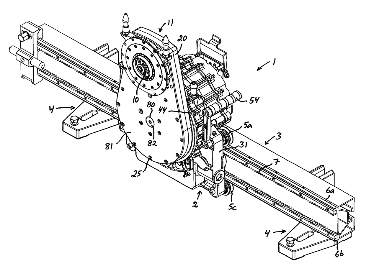
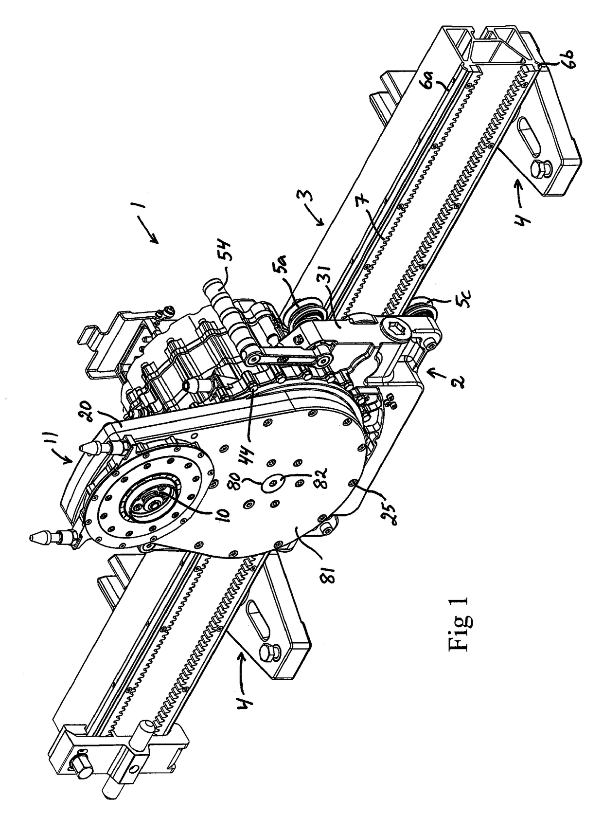
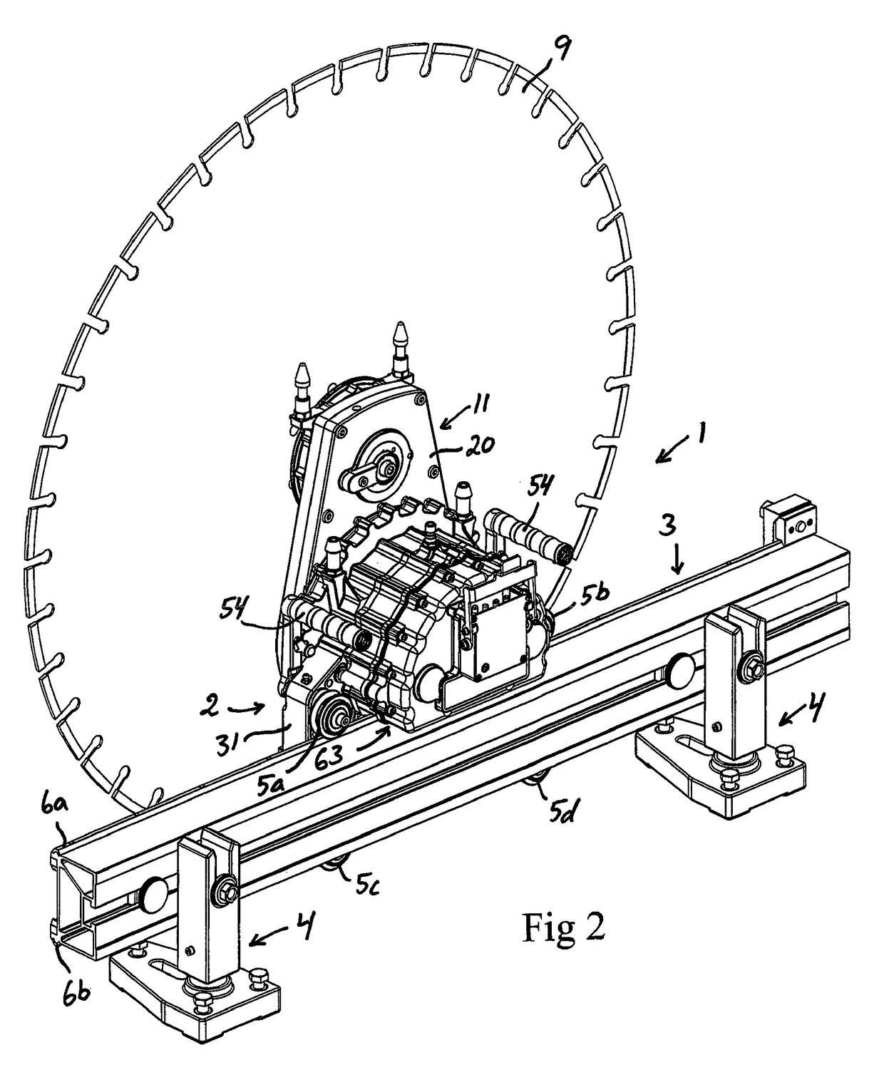
[0033]A wall saw 1 according to an embodiment of the present invention is illustrated in FIGS. 1 and 2. This wall saw 1 is primarily intended to be used for cutting walls, ceilings or floors made of concrete or similar materials. The wall saw 1 comprises a carriage 2, which is to be mounted to an elongated guide rail 3 so as to be moveable along the guide rail. The guide rail 3 is mounted to a floor or other supporting surface by means of support members 4, which are secured to the guide rail 3.

[0034]Guide rollers 5a-5d are rotatably mounted to the carriage 2. These guide rollers 5a-5d are in engagement with guide tracks 6a, 6b on the guide rail 3 and are arranged to keep the carriage 2 in place on the guide rail 3, while allowing the carriage 2 to move along the guide rail 3 in the longitudinal direction thereof. In the illustrated embodiment, the guide rail 3 is provided with an upper guide track 6a and a lower guide track 6b, which extend in parallel with each other along the gui...


PUM

PropertyMeasurementUnit
torqueaaaaaaaaaa
spring forceaaaaaaaaaa
thresholdaaaaaaaaaa

Abstract

A wall saw comprising:—a carriage (2);—a saw arm (11) pivotally mounted to the carriage;—a rotatable spindle (10) rotatably mounted to the saw arm and configured for connection to a saw blade; and—an electric drive motor (13) for rotating the spindle. The rotor (36) of the drive motor comprises a rotor hub (66) which is operatively connected to the output shaft (14) of the drive motor through a safety clutch (67) so as to allow torque to be transmitted from the rotor hub to the output shaft via the safety clutch, the safety clutch being configured to allow mutual rotation between the rotor hub (66) and the output shaft (14) when said torque reaches a given threshold value. The safety clutch (67) is accommodated in a space inside the rotor hub (66).

Description

CROSS REFERENCE TO RELATED APPLICATIONS[0001]The present application is a national phase entry under 35 U.S.C. §371 of International Patent Application No. PCT / SE2013 / 050404, entitled “WALL SAW WITH SAFETY CLUTCH,” filed Apr. 12, 2013. The entire content of International Patent Application No. PCT / SE2013 / 050404 is hereby incorporated by reference in its entirety.FIELD OF THE INVENTION AND PRIOR ART[0002]The present invention relates to a wall saw according to the preamble of claim 1.[0003]A wall saw is a sawing machine primarily used for cutting walls, ceilings or floors made of concrete or similar materials. A conventional wall saw comprises a carriage which is moveable along a guide rail by means of a feeding device. A saw blade is mounted to a spindle, which is rotatably mounted to a saw arm. The saw arm is in its turn pivotally mounted to the carriage. The spindle is rotated by means of a drive motor, which is mounted to the carriage and operatively connected to the spindle thro...

Claims


Application Information

Patent Timeline
Patent Type & Authority Patents(United States)
IPC IPC(8): B28D1/04F16D7/02B23D47/12
CPCB28D1/045B23D47/12B28D1/044F16D7/027
Inventor JOHNSEN, ANDERS
Owner TRACTIVE
Learn More