Eureka AIR delivers breakthrough ideas for toughest innovation challenges, trusted by R&D personnel around the world.

Blade root attachment apparatus and method

Active Publication Date: 2017-04-18
SKYWORKS GLOBAL INC
View PDF21 Cites 4 Cited by
  • Summary
  • Abstract
  • Description
  • Claims
  • Application Information

AI Technical Summary

Benefits of technology

The patent text describes a feathering spindle that connects a rotor blade to a hub. The feathering spindle provides rigidity and supports the rotation of the rotor blade. It also allows for adjustments to the blade's pitch. The patent text also describes an oil circulation system that allows oil to pass through the feathering spindle to lubricate its bearings and regulate its temperature. The system also includes seals to prevent leaks and warm air to aid in maintaining the feathering spindle's temperature and provide anti-icing capabilities. The rotor blade is secured to the hub using bolts and thrust flanges. Overall, the technical effects of the patent text include providing a rigid connection between the rotor blade and hub, allowing for rotation, and providing a lubrication system for the feathering spindle.

Problems solved by technology

Although typical rotorcraft provide the significant advantage of vertical takeoff and landing (VTOL), they are much more limited in their maximum flight speed than are fixed-wing aircraft.
If left uncheck, this disproportionate lift may render the rotorcraft unflyable.
This, in turn, reduces the lift generated by the advancing blade.
This, in turn, increases the lift generated by the retreating blade.
However, lift equalization due to flapping is limited by retreating blade stall.
At certain higher speeds in the direction of flight, the increase in the blade angle of attack required to equalize lift results in loss of lift (stalling) of the retreating blade.
Accordingly, helicopters are quite limited in how fast they can fly.
In autogyro aircraft, the tips of the advancing blades are also subject to this increased drag, even for flight speeds much lower than the speed of sound.
Nevertheless, the same drag increase occurs eventually.

Method used


Image

  • Blade root attachment apparatus and method
  • Blade root attachment apparatus and method
  • Blade root attachment apparatus and method

Examples


Embodiment Construction

[0051]It will be readily understood that the components of the present invention, as generally described and illustrated in the drawings herein, could be arranged and designed in a wide variety of different configurations. Thus, the following more detailed description of the embodiments of the system and method of the present invention, as represented in the drawings, is not intended to limit the scope of the invention, as claimed, but is merely representative of various embodiments of the invention. The illustrated embodiments of the invention will be best understood by reference to the drawings, wherein like parts are designated by like numerals throughout.

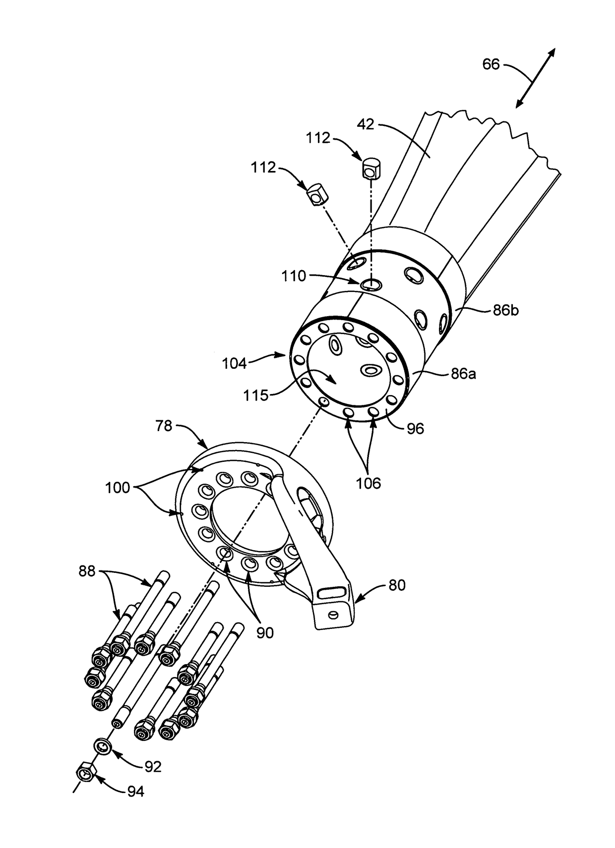
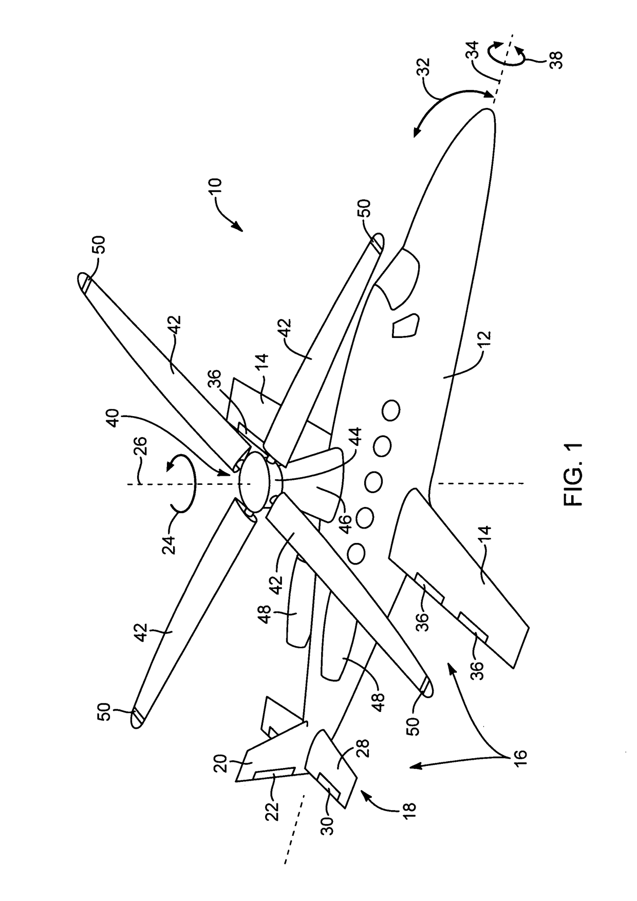
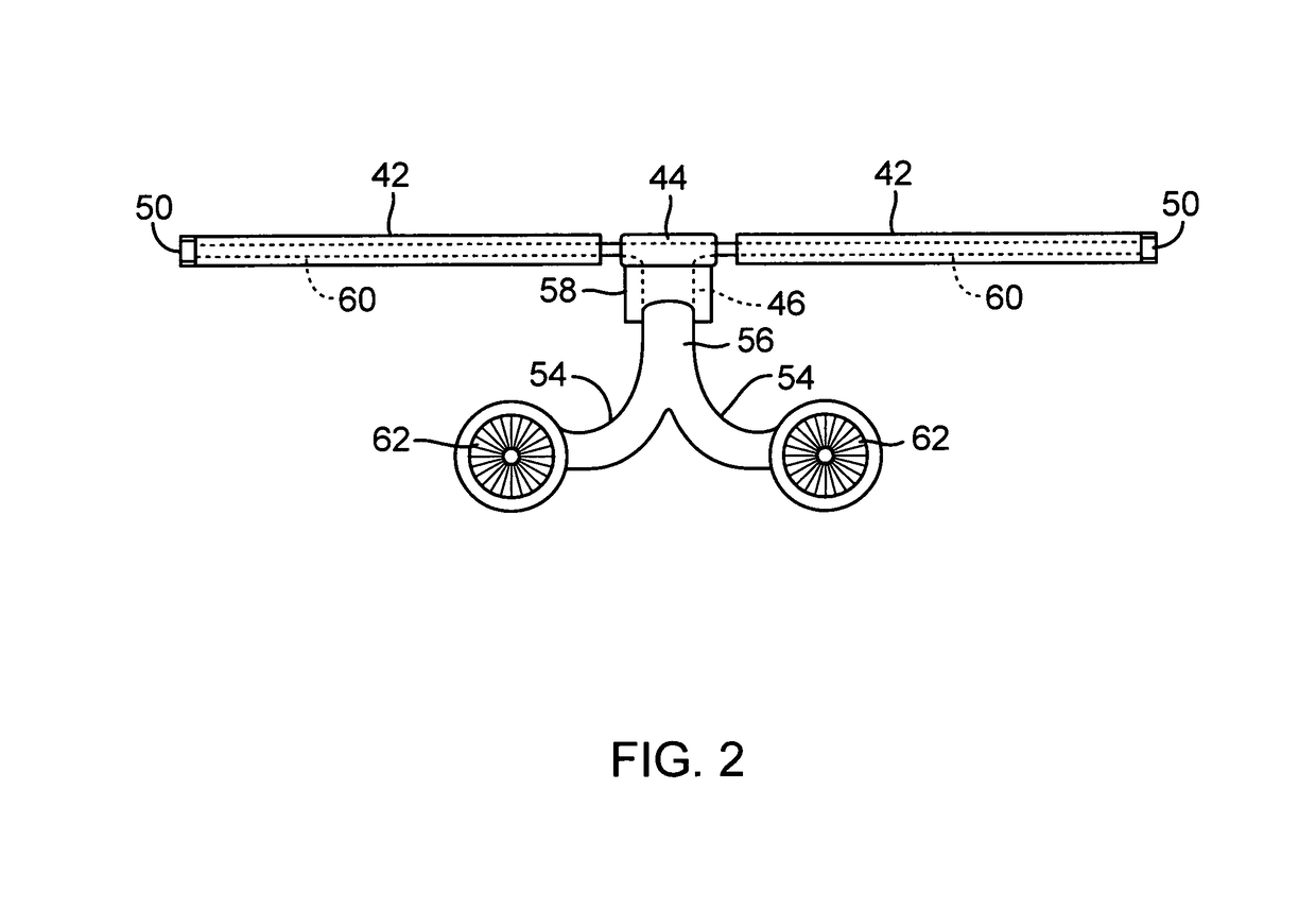
[0052]Referring to FIG. 1, a rotorcraft 10 in accordance with the present invention may include an airframe 12 defining a cabin for carrying an operator, passengers, cargo, or the like. The airframe 12 may include one or more fixed wings 14 or airfoils 14 providing lift to the rotorcraft 10. The wings 14 may be configured such t...


PUM


Abstract

The rotorcraft may include an airframe, at least one engine connected to the airframe, and a rotor connected to the airframe. The rotor may include a hub, a rotor blade, and a feathering spindle connected to the hub. The rotor blade may have a root and a tip and form a conduit extending in the radial direction from the root to the tip. The root may comprise a wall forming a hollow circular cylinder. The hollow circular cylinder may form a portion of the conduit. A plurality of bolts may be distributed circumferential within the wall of the root. The plurality of bolts may extend in the radial direction from the wall of the root to secure the rotor blade to the feathering spindle.

Description

RELATED APPLICATIONS[0001]This application: is a divisional (continuation) of U.S. patent application Ser. No. 13 / 199,705, filed Sep. 7, 2011 and due to issue Mar. 10, 2015 as U.S. Pat. No. 8,973,863; which claims the benefit of U.S. Provisional Patent Application Ser. No. 61 / 403,135, filed Sep. 9, 2010, both of which are hereby incorporated by reference.[0002]Additionally, this patent application hereby incorporates by reference U.S. Pat. No. 5,301,900 issued Apr. 12, 1994 to Groen et al., U.S. Pat. No. 1,947,901 issued Feb. 20, 1934 to J. De la Cierva, and U.S. Pat. No. 2,352,342 issued Jun. 27, 1944 to H. F. Pitcairn.RIGHTS OF U.S. GOVERNMENT[0003]This invention was made with Government support under Agreement No. HR0011-06-9-0002 awarded by DARPA. The Government has certain rights in the invention.BACKGROUND[0004]The Field of the Invention[0005]This invention relates to rotorcraft and, more particularly, to novel systems and methods for securing rotor blades to a hub on high-adv...

Claims


Application Information

Patent Timeline
IPC IPC(8): B64C27/48B64C27/18
CPCB64C27/18B64C27/48B64C27/32
Inventor VAN DER WESTHUIZEN, JACOB JOHANNES
Owner SKYWORKS GLOBAL INC
Why Eureka
Eureka Blog
Learn More