Image-stabilized long-range optical device

a long-range optical and image stabilization technology, applied in the direction of vibration suppression adjustment, instruments, springs/dampers, etc., can solve the problem that the stabilization system cannot compensate for perturbing signals

Active Publication Date: 2017-04-18
CARL ZEISS SMT GMBH
View PDF22 Cites 6 Cited by
  • Summary
  • Abstract
  • Description
  • Claims
  • Application Information

AI Technical Summary

Benefits of technology

[0011]The long-range optical device according to the invention employs the concept of equipping the stabilization system with an eddy current damper for damping oscillations of the at least one movable element, so that in contrast to damping devices based on fluid friction the initial friction is low. By any initial friction, the stabilization system is frictionally coupled to the housing in the event of small signals, so that the stabilization system cannot compensate for the perturbing signals. This is avoided by the use of an eddy current damper. By virtue of the dependency of the restoring force on the amplitude of the displacement of the at least one movable optical element, depending on the configuration of the eddy current damper, for example, larger displacements of the at least one movable optical element may be damped more strongly. The eddy current damper may, however, also be configured in such a way that the at least one movable optical element is carried along in an improved way in the event of intended panning of the long-range optical device, when the user wishes to move the view through the long-range optical device over terrain.
[0056]The advantage achieved by this is that the damping characteristic is adjustable, and in particular can be varied manually, either during production of the long-range optical device or during use of the long-range optical device by a user.

Problems solved by technology

By any initial friction, the stabilization system is frictionally coupled to the housing in the event of small signals, so that the stabilization system cannot compensate for the perturbing signals.

Method used


Image

  • Image-stabilized long-range optical device
  • Image-stabilized long-range optical device
  • Image-stabilized long-range optical device

Examples


Embodiment Construction

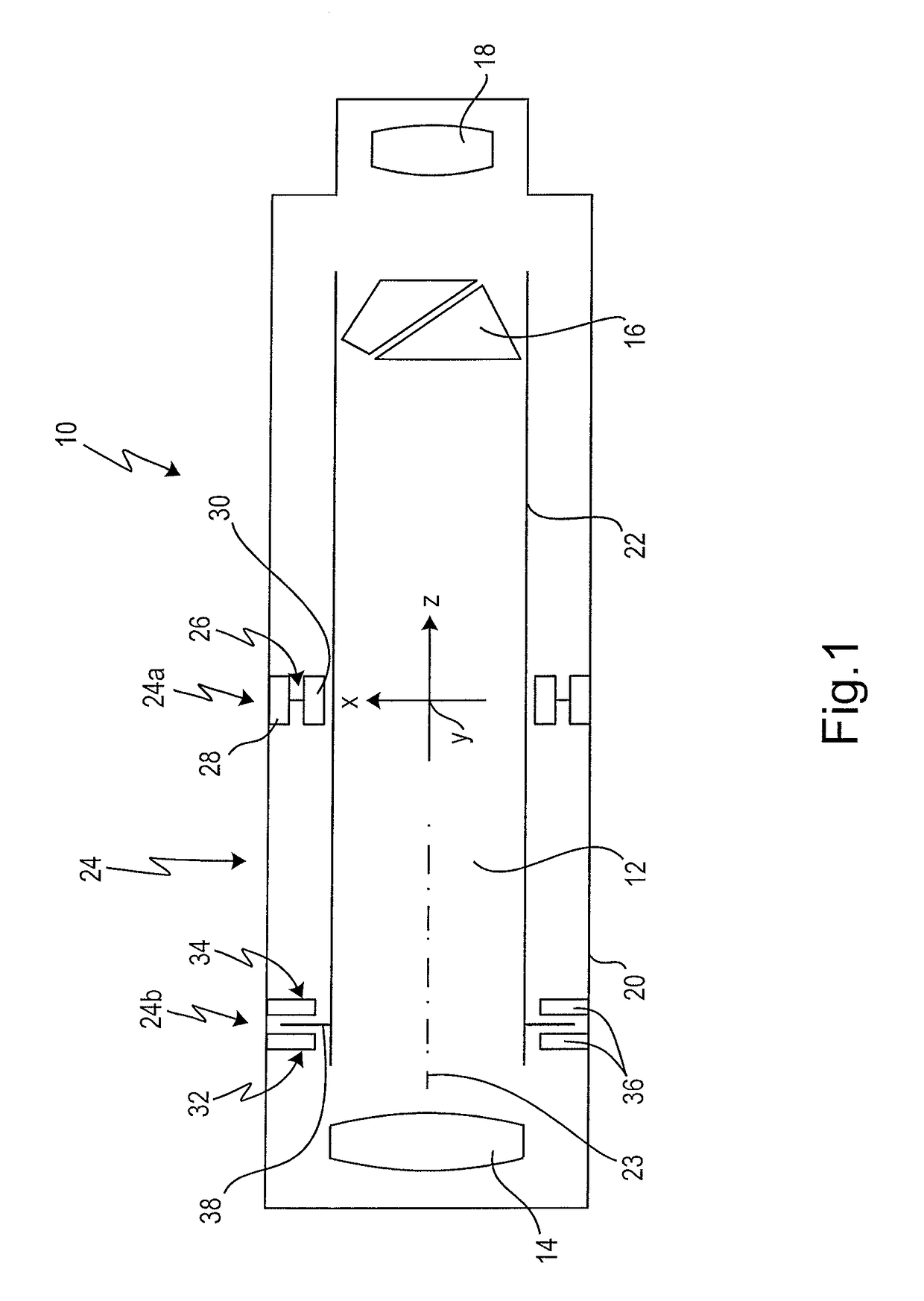
[0090]FIG. 1 shows the basic structure of a long-range optical device, provided with the general reference 10, which is equipped with image stabilization.

[0091]The long-range optical device 10 may be formed as a binocular or monocular telescope, in particular as binoculars. In the case of a monocular telescope, the long-range optical device has one optical channel 12. In the case of configuration of the long-range optical device 10 as a binocular telescope, the long-range optical device 10 correspondingly has a second optical channel, which is not represented in FIG. 1.

[0092]Optical elements 14, 16 and 18 are arranged in the optical channel 12. The optical elements 14, 16 and 18 are represented in a simplified way here, the optical element 14 forming the objective lens, the optical element 16 forming the image inverting system, and the optical element 18 forming the eyepiece of the long-range optical device 10. The optical channel 12 has a housing 20, in which the arrangement of the...


PUM


Abstract

A long-range optical device has at least one optical channel which comprises a housing and an arrangement of optical elements. At least one of the optical elements is movable relative to the housing for image stabilization in the event of perturbing movements of the housing. The device further comprises a stabilization system for the at least one movable optical element, which has an eddy current damper for damping movements of the at least one movable element. The stabilization system, in the event of a displacement of the at least one movable optical element, generates a restoring force proportional to the displacement velocity of the at least one movable optical element. The eddy current damper comprises a magnet system and an eddy current carrier interacting therewith. The restoring force generated by the eddy current damper is dependent on the amplitude of the displacement of the at least one movable optical element.

Description

CROSS REFERENCES TO RELATED APPLICATIONS[0001]This application is a continuation of international patent application PCT / EP2013 / 050176, filed on January 8 designating the U.S., which international patent application has been published in German language and claims priority from German patent application No. 10 2012 000 858.9, filed on Jan. 13, 2012, and from U.S. provisional patent application No. 61 / 586,315 filed on Jan. 13, 2012. The entire contents of these priority applications are incorporated herein by reference.BACKGROUND OF THE INVENTION[0002]The invention relates to a long-range optical device. A long-range optical device may, in the context of the present invention, be a monocular or binocular telescope, in particular binoculars.[0003]During the use of a long-range optical device, for example binoculars, perturbing movements of the housing of the long-range optical device have a detrimental effect on the image quality of the image seen by the user. The perturbing movements...

Claims


Application Information

Patent Timeline
Patent Type & Authority Patents(United States)
IPC IPC(8): G02B27/64F16F15/03G02B23/02
CPCG02B27/646F16F15/035G02B27/644G02B23/02
Inventor DOBERMANN, DIRKROBOTTA, RAINERGUENTHER, GEORGHOFMANN, JENSBECKER, KURTROTH, ECKHARDTHIELE, TOBIAS
Owner CARL ZEISS SMT GMBH
Why Eureka
Try Eureka