Support apparatus for an exercise device

a technology for supporting apparatus and exercise devices, which is applied in the direction of show stands, show hangers, and display shelves, etc., can solve the problem of prohibitively expensiv

Inactive Publication Date: 2017-04-25
ESCAPE FITNESS
View PDF9 Cites 8 Cited by
  • Summary
  • Abstract
  • Description
  • Claims
  • Application Information

AI Technical Summary

Benefits of technology

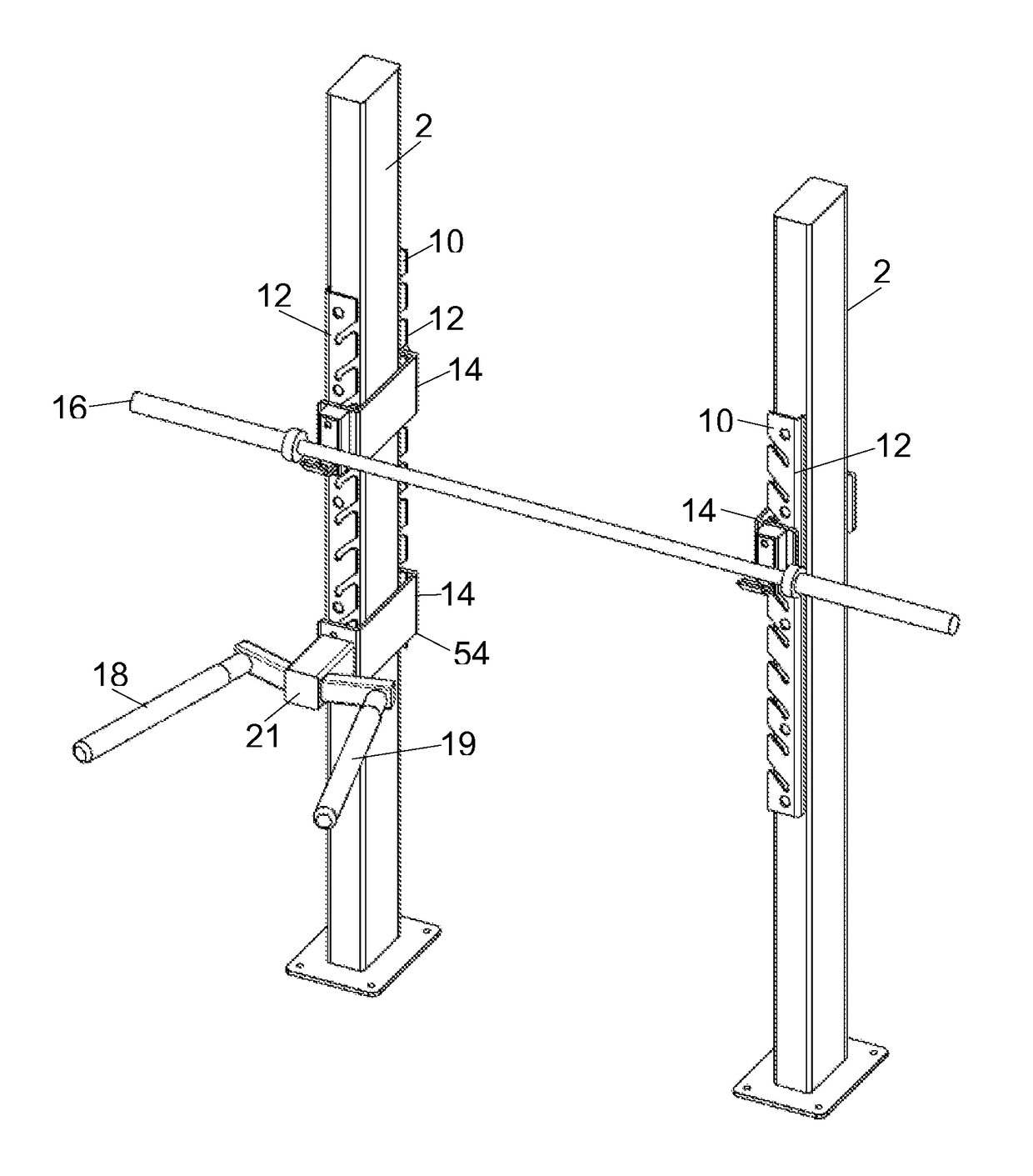
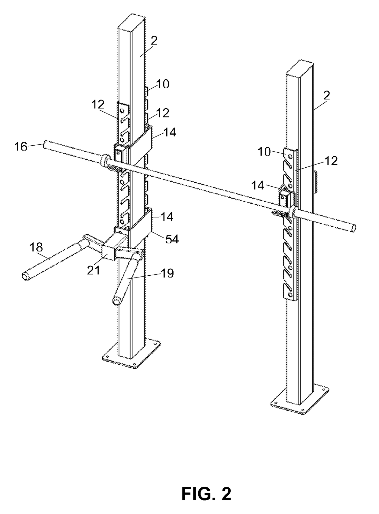
[0010]The bracket is intended to support heavy weights and / or all or part of a user's weight during use. It is therefore important that lateral movement of the bracket is prevented to avoid the shifting of weights or to avoid the anchor for a user moving when a force is applied to it by a user. It is not possible to form the bracket such that it engages the outer surfaces of the racks to prevent lateral movement as this would rely on a high tolerance in the width of the upright legs which would be prohibitively expensive. The invention provides a first locating member that locates on the rack at a single position along its length defined by the lateral locating element and laterally secures to the rack such that lateral movement of the bracket is prevented achieves the required lateral restriction. The second locating member is freely movable relative to the corresponding rack and is therefore able to locate into the corresponding channel at any point along its length, thereby accommodating any variances in the width the rack section due to a variance in tolerance of the width of the frame upright to which the rack sections are secured.
[0013]The locating members may comprise cylindrical projections having a diameter corresponding to the width of the channels of the rack sections such that the projections are able to slide within the channels. The cylindrical configuration, which may be solid o hollow, allows the projections to slide and be easily received within the channels at any angular orientation. The lateral engagement element may comprise two sections of increased diameter spaced along the at least one projection including the lateral engagement element. The increased diameter sections are preferably formed integrally with the bar, such as by turning down a reduced diameter section from a cylindrical bar. Alternatively, the increased diameter sections may be separate components fixed to the smaller diameter projection.
[0016]Each channel is preferably configured such that when the rack section is vertically oriented in use the channels slope downwardly away from the opening. This prevents the brackets from sliding out of the channels in use. The bracket may only be removed if a user intentionally lifts the bracket out of the channels.
[0017]The downwardly sloping section of each channel may substantially straight and the channels are arranged along the rack section such that the straight sections of each channel are parallel to each other thereby ensuring that the projections are able to slide in parallel in vertically adjacent channels.
[0018]Each channel preferably includes a terminal holding section at the opposing end of the channel to the opening that is configured to extend downwardly from the previous section of the channel when the rack section is vertically oriented in use. This acts to laterally lock the bracket in position and prevent lateral movement in the second lateral direction perpendicular to the axis of the projections.

Problems solved by technology

It is not possible to form the bracket such that it engages the outer surfaces of the racks to prevent lateral movement as this would rely on a high tolerance in the width of the upright legs which would be prohibitively expensive.

Method used


Image

  • Support apparatus for an exercise device
  • Support apparatus for an exercise device
  • Support apparatus for an exercise device

Examples


Embodiment Construction

[0035]To facilitate an understanding of the principles and features of the various embodiments of the invention, various illustrative embodiments are explained below. Although exemplary embodiments of the invention are explained in detail, it is to be understood that other embodiments are contemplated. Accordingly, it is not intended that the invention is limited in its scope to the details of construction and arrangement of components set forth in the following description or examples. The invention is capable of other embodiments and of being practiced or carried out in various ways. Also, in describing the exemplary embodiments, specific terminology will be resorted to for the sake of clarity.

[0036]It must also be noted that, as used in the specification and the appended claims, the singular forms “a,”“an” and “the” include plural references unless the context clearly dictates otherwise. For example, reference to a component is intended also to include composition of a plurality ...


PUM


Abstract

A support apparatus for removably connecting fitness equipment to an exercise frame. The support apparatus can include first and second rack sections configured to be fixed in a spaced arrangement to a frame member, each rack section including at least one receiving channel having an opening at one end, and a bracket for supporting the exercise equipment.

Description

CROSS REFERENCE TO RELATED APPLICATIONS[0001]This application claims the benefit of UK Patent Application No. 1316889.3, filed 23 Sep. 2013, the entire contents and substance of which is hereby incorporated by reference.BACKGROUND OF THE INVENTION[0002]1. Field of the Invention[0003]The present invention relates to an exercise device support apparatus, and in particular a support apparatus for removably connecting exercise equipment to an exercise frame.[0004]2. Description of Related Art[0005]The increase in the number and variety of exercise equipment and the variety of ways in which exercises may be performed using this equipment has presented fitness clubs and gyms with the problem of accommodating such equipment and providing the space for such a wide range of exercise activities. A typical gym environment will include one or more rooms including a variety of fitness equipment located across the floor space. The fitness equipment may comprise fixed apparatus for performing a sp...

Claims


Application Information

Patent Timeline
Patent Type & Authority Patents(United States)
IPC IPC(8): A47F7/00A63B21/078A63B17/04A63B23/12A63B21/00
CPCA63B21/078A47F7/00A63B17/04A63B21/00047A63B23/1227A63B2225/09A63B2225/093
Inventor CHILDS, MARTIN
Owner ESCAPE FITNESS
Why Eureka
Try Eureka