
Nut for providing quick assembly and disassembly

a technology of quick assembly and disassembly, which is applied in the direction of water installations, constructions, fastening means, etc., can solve the problems of difficult rotation of the nut, limited width of each limiting portion, and repeated and troublesome rotation of the conventional nu

Inactive Publication Date: 2017-05-02
GLOBE UNION INDAL
View PDF10 Cites 11 Cited by
  • Summary
  • Abstract
  • Description
  • Claims
  • Application Information

AI Technical Summary

Benefits of technology

This patent describes a nut that can be easily assembled and disassembled compared to conventional nuts. The nut has flexible retaining portions that are mounted on an external driving member and can expand and contract. The nut is fixed and removed by holding the external driving member, which makes it easy and comfortable for the user. The main technical effects of this patent are improved assembly and disassembly of the nut, increased security of the faucet or kitchen basin, and improved user experience.

Problems solved by technology

However, when fixing the faucet in a narrow space, the conventional nut is rotated repeatedly and troublesomely.
To fix the faucet on the basin, some screwing tubes are prolonged, thus rotating the nut difficultly.
Nevertheless, a width of each limiting portion is limited, and a meshing area between the threaded section and the screwing tube is quite small, thus casing poor screwing effect.
But the at least one locking block is limited and cannot arrange circumferentially, so the user cannot press each limiting portion inwardly because of limited space, and each abutting portion of the second sleeve member cannot pass through a cutout or a size of each abutting portion is reduced.
Accordingly, the first sleeve member cannot be held comfortably.
However, when the length of the screwing tube is short and a thickness of the basin is large, the screwing tube cannot screw with the nut.

Method used


Image

  • Nut for providing quick assembly and disassembly
  • Nut for providing quick assembly and disassembly
  • Nut for providing quick assembly and disassembly

Examples


first embodiment

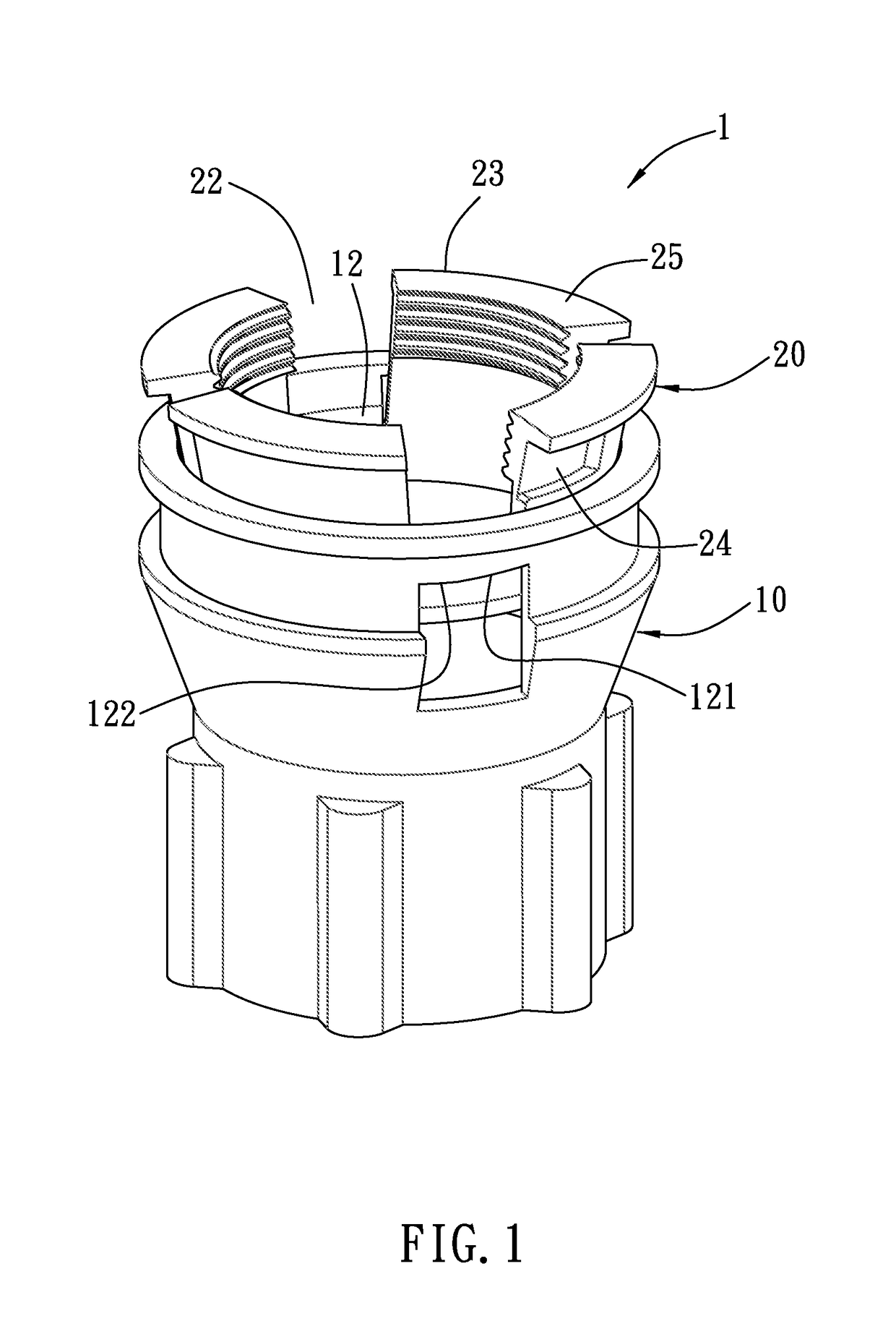
[0038]With reference to FIGS. 1 and 13, a nut 1 according to the present invention is employed to fix a faucet on a wash basin 2 or a kitchen basin 2, the faucet is a bath faucet or a kitchen faucet and includes a screwing tube 3 disposed on a lower side thereof and extending out of a bottom fence 2b of the wash basin 2 or the kitchen basin 2 via a fixing hole 2a.

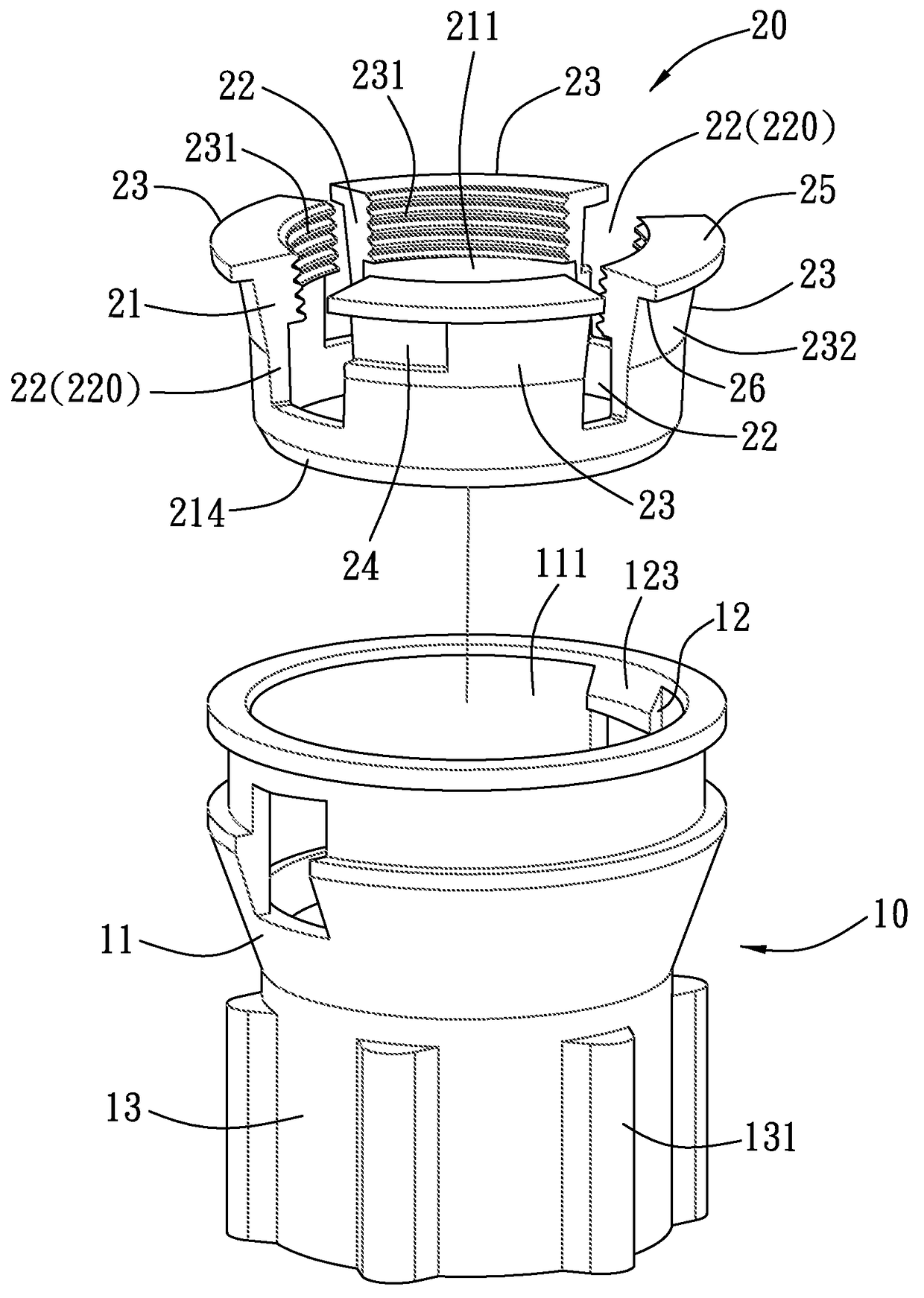
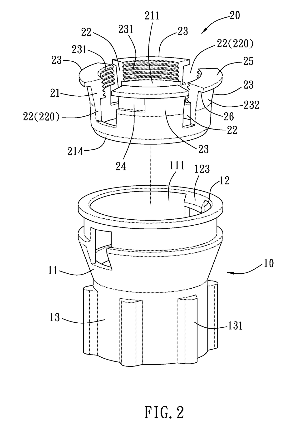
[0039]Referring further to FIGS. 2 to 6, the nut 1 for providing quick assembly and disassembly comprises an external driving member 10 and an internal screwing member 20.

[0040]The external driving member 10 is in a sleeve shape and includes a cylindrical fence 11 and an accommodating cavity 111 defined on at least an upper side of the cylindrical fence 11, a first edge 112 formed around a top surface of the cylindrical fence 11, and a second edge 113 arranged around a bottom surface of the cylindrical fence 11.

[0041]As shown in FIG. 3, the cylindrical fence 11 has at least one limiting block 12 extending outwardly from an...

second embodiment

[0068]It is to be noted that when each limiting block 12 of second embodiment is rotatably slid into each peripheral groove 24 to drive the internal screwing member 20 to rotate, and the faucet is fixed on the wash basin so that the external driving member 10 is released by the user and is pushed by a plurality of flexible retaining portions 23 to move downwardly, thereafter the locking protrusion 124 of each limiting block 12 retains into the locking indentation 241 to limit each limiting block 12 to rotatably remove from each peripheral groove 24.

[0069]As desiring to remove each limiting block 12, the external driving member 10 is pushed and pressed upwardly so that the locking protrusion 124 of each limiting block 12 moves upwardly to remove from the locking indentation 241 of each peripheral groove 24, thereafter the locking protrusion 124 of each limiting block 12 is rotated back, thus removing the locking protrusion 124 from each peripheral groove 24.

third embodiment

[0070]As illustrated in FIG. 16, a nut 1 according to the present invention comprises at least one limiting block 12 and at least one peripheral groove 24, and each peripheral groove 24 has a locking indentation 241, wherein each limiting block 12 has a sliding surface 121 and a locking protrusion 124 formed behind the sliding surface 121, such that each limiting block 12 has the sliding surface 121 for providing guiding and sliding function and has the locking protrusion 124 for retaining in the locking indentation 241 of each peripheral groove 24.

[0071]Thereby, the nut 1 of the present invention has advantages as follows:

[0072]1. When the external driving member 10 is located at the releasing position P1, the plurality of flexible retaining portions 23 of the internal screwing member 20 are in the flexible expending state to allow inserting through the screwing tube 3, and as desiring to fix the faucet, the external driving member 10 is pushed and pressed upwardly, the internal sc...


PUM


Abstract

A nut is employed to fix a faucet on a wash basin or a kitchen basin and contains an external driving member and an internal screwing member. The external driving member includes a cylindrical fence, an accommodating cavity, a first edge, and a second edge; the cylindrical fence has at least one limiting block and a griping face. The internal screwing member is fitted into and retained with the accommodating cavity and includes an annular cliff, a through orifice, a third edge, and a fourth edge; the annular cliff has plural slots longitudinally extending and isometrically arranged to the fourth edge from the third edge so as to define a plurality of flexible retaining portions, each having an inner threaded section; the annular cliff also has at least one longitudinal recess for retaining with the at least one limiting block of the external driving member and has a contacting fringe.

Description

FIELD OF THE INVENTION[0001]The present invention relates to a nut for providing quick assembly and disassembly.BACKGROUND OF THE INVENTION[0002]A bath faucet or a kitchen faucet contains a screwing tube or a screw rod, such that the screwing tube is inserted through a fixing hole of a basin and then is screwed with a conventional nut, thereafter the nut abuts against a bottom fence of the basin, thereby fixing the faucet on the basin.[0003]However, when fixing the faucet in a narrow space, the conventional nut is rotated repeatedly and troublesomely. To fix the faucet on the basin, some screwing tubes are prolonged, thus rotating the nut difficultly.[0004]To solve above-mentioned problem, CN Publication No. 201206582Y disclosed a quick nut contains a first sleeve member and a second sleeve member. The first sleeve member has two limiting portions disposed on a bottom end thereof and expending and retracting flexibly, the first sleeve member is inserted through an orifice of the sec...

Claims


Application Information

Patent Timeline
Patent Type & Authority Patents(United States)
IPC IPC(8): F16B37/08E03C1/04
CPCF16B37/0864E03C1/0401Y10T403/535
Inventor LIN, YIPINGYANG, CHAOTAHONG, CHUWAN
Owner GLOBE UNION INDAL
Learn More