System and method for automatically controlling one or multiple turbogenerators

a turbogenerator and automatic control technology, applied in the direction of electric generator control, positive displacement liquid engine, pump parameter, etc., can solve the problems of high complexity of system, development of ad hoc architectures, and further increase of integration effor

Active Publication Date: 2017-05-02
TURBINE POWERED TECH LLC
View PDF50 Cites 120 Cited by
  • Summary
  • Abstract
  • Description
  • Claims
  • Application Information

AI Technical Summary

Problems solved by technology

The development of highly complex systems typically involves the use of multiple specialized vendors to design and manufacture specific, stand-alone components that are then integrated into the system.
The complexity of the integration effort is further increased where the same component needs to be integrated with multiple disparate platforms.
The complexity of integrating components into sophisticated systems can lead to the development of ad hoc architectures.
Popularly called “stovepipes,” such systems use point-to-point integration and can lack coordination and planning across multiple systems.
Thus, prior integration efforts are often duplicated and the resulting system can suffer with a costly, unmaintainable, and unextendable architecture.
The need to satisfy strict industry testing and certification regulations can turn the process of replacing or upgrading a mundane component into a substantial implementation-specific development effort, resulting in additional costs and time delays.
Because the driving force of each integration effort is the characteristics of the given system, the architecture of each resulting interface can be fragile and limited in terms of reusability or adaptability.
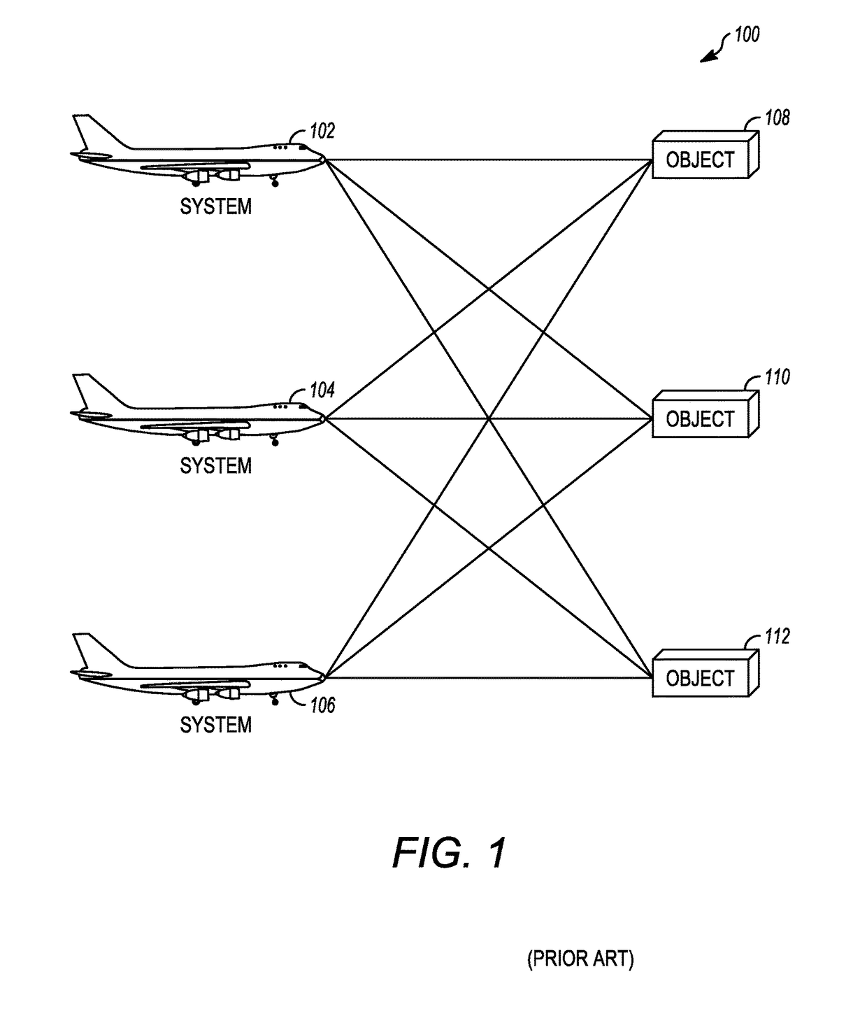
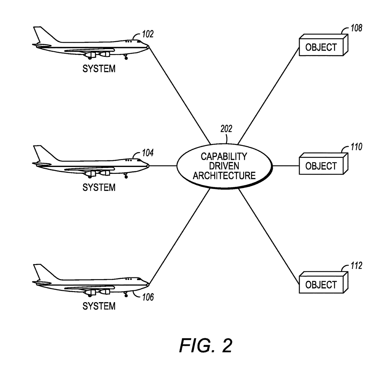
The ultimate result is the undertaking of nine duplicative, costly and time consuming, implementation-specific design efforts (illustrated by the connecting lines in FIG. 1) to integrate each object with each system.
Where the systems are for use in safety-critical, mission-critical, or other regulated applications, each object-system implementation may further require verification and certification before release, with the extensive testing required further increasing costs and time delays.

Method used


Image

  • System and method for automatically controlling one or multiple turbogenerators
  • System and method for automatically controlling one or multiple turbogenerators
  • System and method for automatically controlling one or multiple turbogenerators

Examples


implementation example # 1

Implementation Example #1: Radios

[0066]The following example is presented to further illustrate to persons skilled in the art how to make and use one embodiments of this disclosure. This example is not intended as a limitation, however, upon the scope of the invention, which is defined only by the appended claims.

[0067]By way of example and not limitation, it may be desirable to exchange one radio with another in an aircraft without developing separate radio-specific control interfaces. Specifically, it may be determined that three military radios, RADIO A produced by Company A, RADIO B produced by Company B, and RADIO C produced by Company C, need to be interchangeable with one another without having to alter the interface between the currently installed radio and the aircraft.

[0068]Once the group of radios to be integrated is defined, the ICDs for the radios are examined. While it is not necessary for all the ICDs for each radio in the group be used, it will be understood by one o...

implementation example # 2

Implementation Example #2: Gas Turbine Engine Control with (Optional) Multi-Compatibility

[0083]As another example, the architecture of FIGS. 3-4 may be applied to the task of digitally controlling one or more engines. Although this is applicable to any engine, this example is discussed in the context of a gas turbine engine such as the engine 600 of FIG. 6. This engine 600 includes an N2 rotating system 602, a combustion stage 604, a compressor stage 606, speed / torque sensor 608, and N2 output power 610. A controller, which in this example uses the capability driven architecture described herein above, is embodied by item 616. The controller receives data from the engine 600 via at least one feedback line 612, and sends control signals to the engine 600 on at least one control line 614. The controller 616 may be implemented in different ways, with one example being an integration of FPGA circuit, microprocessor, memory, and various I / O lines, using a custom operating system and vari...

implementation example # 3

Implementation Example #3: Gas Turbine Engine Control with Auto Detect

[0098]A further exemplary application of the present disclosure involves an engine controller with an engine auto detect feature. Although this is applicable to any engine, this example is discussed in the context of gas turbine engines as described above in FIGS. 6, 7, and 12.

[0099]In contrast with the previous example, this scenario includes a data source 1212 (FIG. 12) physically attached to, or otherwise associated with, the engine 600. The data source 1212 is referred to as a “bullet” herein. Broadly, the bullet 1212 identifies the variant, such as make / model, of the engine 600 to the controller 616. The bullet 1212 and engine controller 616 communicate via a path 1210. The bullet 212 may also serve to store further data in support of the controller 616's functions, as explained below.

[0100]The bullet may be a passive storage device, a continually active transmitter or broadcaster of data, or a data transmitt...


PUM


Abstract

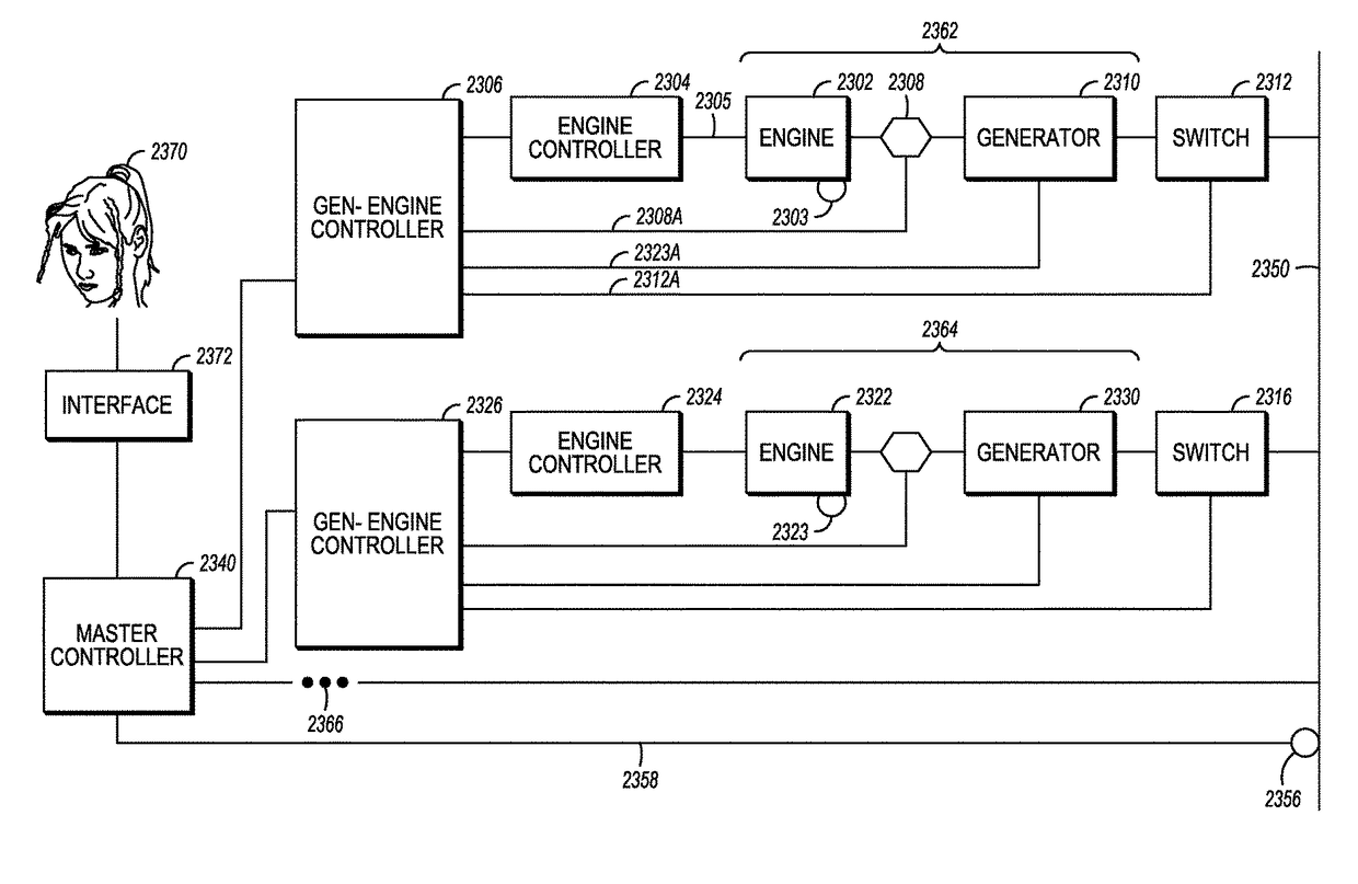
At least one controller manages a gas turbine engine driving a generator directly or indirectly coupled to the engine. The controller is programmed to automatically determine and adjust inputs to the gas turbine engine in order to cause the generator to produce a user-specified electrical output. Multiple sets of generator, engine, and controller may be used, in which case a master controller individually manages the other controllers to collectively provide the a user-specified electrical output.

Description

CROSS-REFERENCE TO RELATED APPLICATIONS[0001]This application claims the benefit of the following earlier-filed U.S. Provisional Application in accordance 35 USC 119: Application No. 61 / 781,493, filed Mar. 14, 2013, entitled “METHODS AND SYSTEMS FOR DIGITALLY CONTROLLING TURBINE ENGINES.” The entirety of the foregoing provisional application is hereby incorporated herein by reference.BACKGROUND OF THE INVENTION[0002]1. Field of the Invention[0003]The present invention relates generally to software and hardware integration, and more particularly to the integration of independent software and hardware products in safety-critical, mission critical, or other regulated applications.[0004]2. Description of the Related Art[0005]The development of highly complex systems typically involves the use of multiple specialized vendors to design and manufacture specific, stand-alone components that are then integrated into the system. Unless an industry standard has been adopted, each stand-alone c...

Claims


Application Information

Patent Timeline
Patent Type & Authority Patents(United States)
IPC IPC(8): F02C6/00F02C6/02H02P9/04
CPCF02C6/00H02P9/04F02C6/02F05D2270/06F02C9/42F04B23/04F04B2201/12F04B2205/05F04B49/06F02C9/00F04B17/00F04D13/02F04D15/0066F02C9/18F02C9/22F02C9/26F05D2270/021
Inventor CROWE, DAVIDCROM, ELDEN
Owner TURBINE POWERED TECH LLC
Why Eureka
Try Eureka