Check patentability & draft patents in minutes with Patsnap Eureka AI!

Soot generating device

a generation device and a technology of soot, applied in the direction of suspension, porous material analysis, structural/machine measurement, etc., can solve the problem that the equipment used for lii and similar techniques is difficult to calibra

Inactive Publication Date: 2017-05-09
ROLLS ROYCE PLC
View PDF12 Cites 1 Cited by
  • Summary
  • Abstract
  • Description
  • Claims
  • Application Information

AI Technical Summary

Benefits of technology

The soot generating device provides a repeatable and constant soot production, enabling precise calibration of soot measuring instruments, improving the accuracy of soot measurement techniques like laser-induced incandescence by providing a reliable calibration standard.

Problems solved by technology

One key pollutant is soot created during the combustion cycle.
However, the equipment used for LII and similar techniques are difficult to calibrate due to the lack of a reliable calibration standard.

Method used


Image

  • Soot generating device
  • Soot generating device
  • Soot generating device

Examples


Embodiment Construction

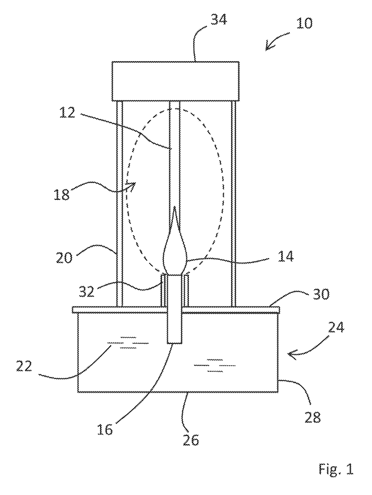
[0016]FIG. 1 shows a soot generating device 10 according to the present invention. The soot generating device 10 produces a repeatable and constant amount of soot 12 for a given fuel type such that is can be used to calibrate a soot measuring piece of equipment (not shown).

[0017]The soot generating device 10 utilises a stable flame 14 to produce soot 12 and includes a wick 16 which is located relative to a burning zone 18 in which the flame 12 sits during normal use. In ordinary use, the wick is located below the burning zone. The burning zone 18 is surrounded by a gas diffusion shield 20 which allows air to pass continuously and evenly into the burning zone 18 for combustion and the production of soot.

[0018]The wick 16 receives fuel 22 from a suitable supply, which in the described embodiment, is provided by a small tank 24 located beneath the burning zone 18 and wick 16 when in normal use. The fuel tank 24 includes a vessel having a base 26, on which the soot generating apparatus ...


PUM

PropertyMeasurementUnit
diameteraaaaaaaaaa
timeaaaaaaaaaa
diameteraaaaaaaaaa

Abstract

A soot generating device suitable for calibration purposes and a method of using the device for calibrating a soot measuring apparatus are presented. The soot generating device includes a wick located relative to a burning zone, a gas diffusion shield surrounding the burning zone that allows a continuous stream of air into the combustion zone, and a fuel supply for delivering fuel to the wick.

Description

TECHNICAL FIELD OF INVENTION[0001]This invention relates to a soot generating device which can produce a known amount of soot.BACKGROUND OF INVENTION[0002]The examination of pollutants in the exhaust streams of combustion engines is increasingly important area of interest. One key pollutant is soot created during the combustion cycle. There are numerous techniques for measuring the soot, some of which are laser based like the well known laser induced incandescence, LII. However, the equipment used for LII and similar techniques are difficult to calibrate due to the lack of a reliable calibration standard. This invention seeks to provide an improved calibration standard.STATEMENTS OF INVENTION[0003]In a first aspect, the present invention provides a soot generating device suitable for calibration purposes, comprising: a wick located relative to a burning zone; a gas diffusion shield surrounding the burning zone, the gas diffusion shield allowing a continuous stream of air into the co...

Claims


Application Information

Patent Timeline
Patent Type & Authority Patents(United States)
IPC IPC(8): G01M15/10G01N21/71G01N5/00G01N15/00G01N15/06
CPCG01M15/108G01N5/00G01N21/71G01N15/0606G01N2015/0046G01N2201/06113G01N2201/127
Inventor BLACK, JOHN DAVID
Owner ROLLS ROYCE PLC
Features
  • R&D
  • Intellectual Property
  • Life Sciences
  • Materials
  • Tech Scout
  • Unparalleled Data Quality
  • Higher Quality Content
  • 60% Fewer Hallucinations
Learn More